Apparatus, system and sensor housing assembly utilizing fiber optic sensors for enabling monitoring operating conditions within a structural member

a technology of fiber optic sensors and sensor housing, which is applied in the field of apparatuses, systems and sensor housing assemblies utilizing fiber optic sensors, can solve the problems of flow restrictions, completely blocking pipelines, and affecting the operation of structural members

Active Publication Date: 2018-03-13
ASTRO TECH GRP LLC
View PDF5 Cites 8 Cited by
  • Summary
  • Abstract
  • Description
  • Claims
  • Application Information

AI Technical Summary

Benefits of technology

[0015]Embodiments of the present invention provide a unique approach to generating operating condition information used for assessing flow assurance and structural integrity. More specifically, apparatuses, systems and sensor housing assemblies configured in accordance with embodiments of the present invention utilize fiber optic sensors for enabling monitoring of operat

Problems solved by technology

As hot gases that flow from the wellhead (i.e., particularly subsea wellheads) are subjected to cooling, hydrates can precipitate from the product and results in flow restrictions and in extreme cases can completely block the pipeline.
In other instances, slow buildup of paraffin wax on the interior of the pipeline can cause flow restrictions.
These blockages and flow restrictions pose significant risk to safe and efficient operation of such pipelines.
Historically, the load cells are unreliable and often fail early in their service life such as due to their expos

Method used


Image

  • Apparatus, system and sensor housing assembly utilizing fiber optic sensors for enabling monitoring operating conditions within a structural member
  • Apparatus, system and sensor housing assembly utilizing fiber optic sensors for enabling monitoring operating conditions within a structural member
  • Apparatus, system and sensor housing assembly utilizing fiber optic sensors for enabling monitoring operating conditions within a structural member

Examples


Embodiment Construction

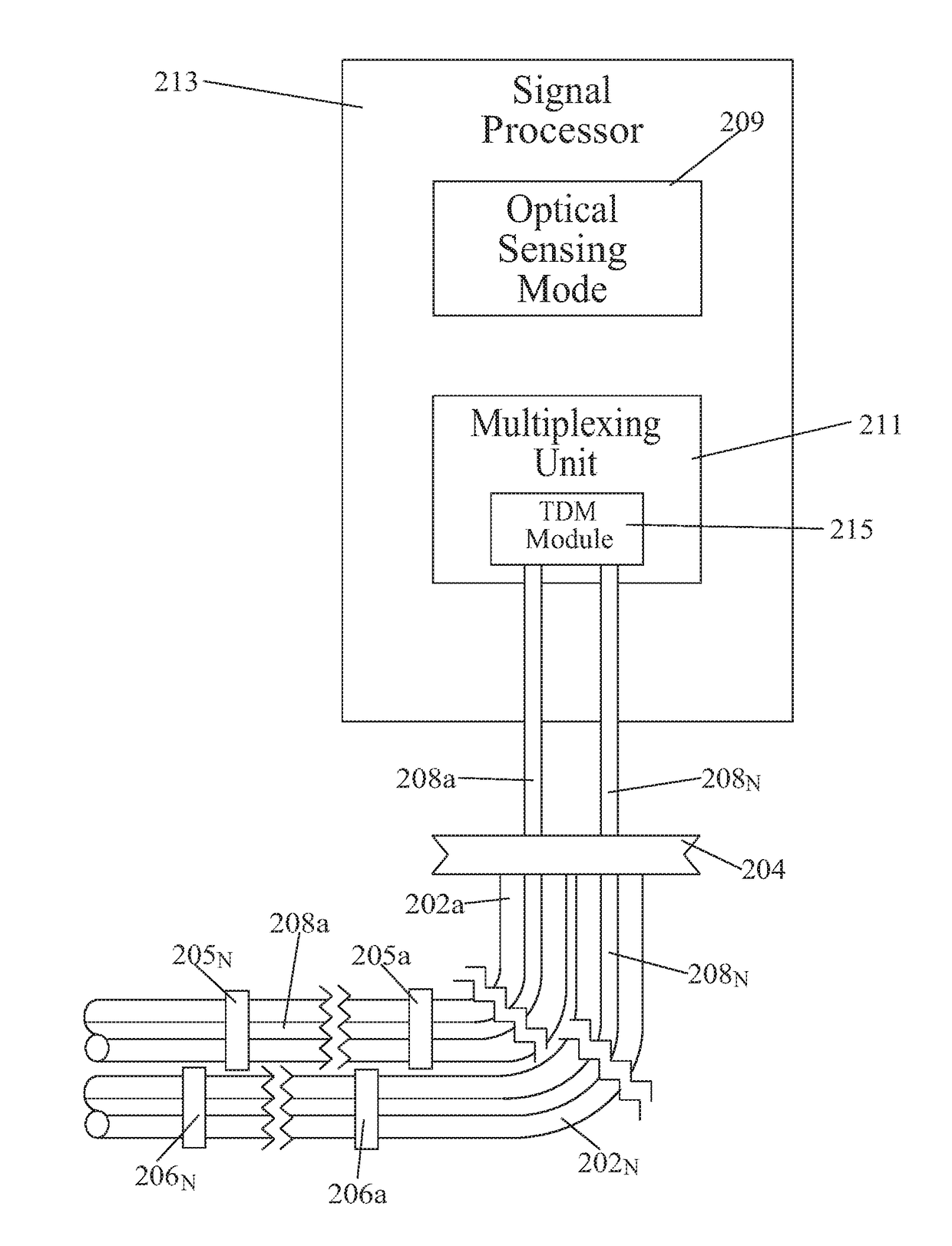
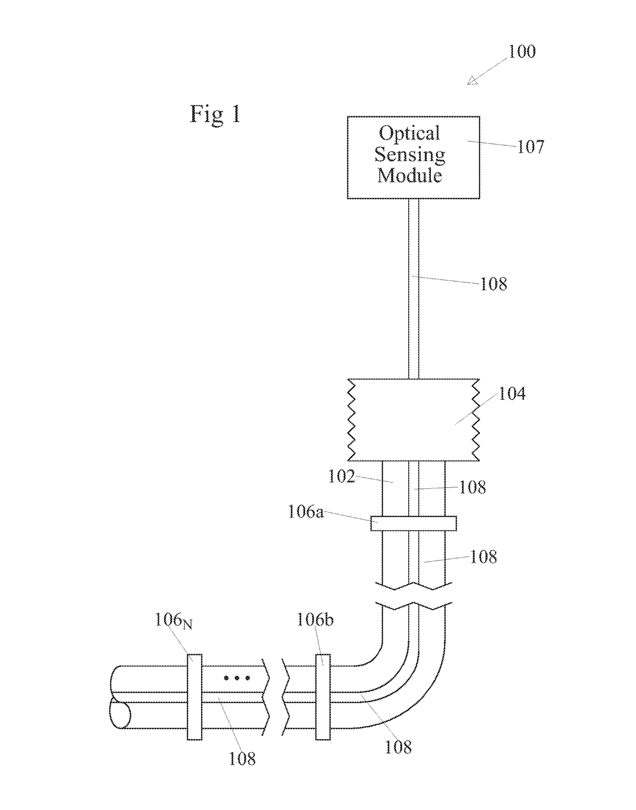
[0038]FIG. 1 shows an apparatus 100 configured in accordance with an embodiment of the present invention. The apparatus 100 includes an elongated tubular member 102 that is connected to a support structure 104. A plurality of sensor housing assemblies 106a-106n are mounted in a spaced-apart arrangement along a length of the elongated tubular member 102. The sensor housing assemblies 106a-106n are connected to each other and to an optical sensing module 107, such as at a signaling port thereof, by a fiberoptic cable 108.

[0039]The sensor housing assemblies 106a-106n, the optical sensing module 107 and the fiberoptic cable 108 jointly provide for operating condition information for the elongated tubular member 102, a fluid within the elongated tubular member 102, or both to be generated, communicated and monitored. As discussed below in greater detail, each one of the sensor housing assemblies 106a-106n includes one or more fiber optic sensors (not specifically shown in FIG. 1) that ar...


PUM


Abstract

Embodiments of the present invention provide a unique new approach to generating operating condition information used for assessing flow assurance and structural integrity. More specifically, apparatuses, systems and sensor housing assemblies configured in accordance with embodiments of the present invention utilize fiber optic sensors for enabling monitoring of operating condition information within one or more elongated tubular members. To this end, such fiber optic sensors are strategically placed at a plurality of locations along a length of each elongated tubular member thereby allowing critical operating conditions such as strain, temperature and pressure of the elongated tubular member and/or a fluid therein to be monitored.

Description

CROSS-REFERENCE TO RELATED APPLICATIONS[0001]This continuation-in-part patent application claims priority from U.S. non-provisional patent application having Ser. No. 13 / 852,896, filed 23 Mar. 2013, entitled “AN APPARATUS TO MONITOR FLOW ASSURANCE PROPERTIES IN CONDUITS”, having a common applicant herewith and being incorporated herein in its entirety by reference.[0002]U.S. non-provisional patent application having Ser. No. 13 / 852,896 is a continuation of and claims priority from U.S. non-provisional patent application having Ser. No. 12 / 882,993 filed 15 Sep. 2010, entitled “APPARATUS TO MONITOR FLOW ASSURANCE PROPERTIES IN CONDUITS”, having a common applicant therewith and being incorporated herein in its entirety by reference.[0003]U.S. non-provisional patent application having Ser. No. 12 / 882,993, claims priority from U.S. provisional patent application having Ser. No. 61 / 242,746, filed 15 Sep. 2009, entitled “APPARATUS TO MONITOR FLOW ASSURANCE PROPERTIES IN CONDUITS”, having a...

Claims


Application Information

Patent Timeline
IPC IPC(8): G01B1/00B63B35/44E02B17/00G01L11/02B63B21/50
CPCG01L11/025B63B35/44E02B17/00B63B21/502E21B47/01
Inventor BROWER, DAVID V.
Owner ASTRO TECH GRP LLC
Why Eureka
Try Eureka