Piezoelectric device, liquid ejecting head, and liquid ejecting apparatus

a liquid ejecting device and ejecting head technology, applied in the direction of printing, inking apparatus, etc., can solve the problems of bias voltage drop, difficulty in sufficiently secure a length, etc., and achieve the effect of reducing the size of the actuator substrate, reducing the space for disposing the adhesive layer, and suppressing the bias voltage variations

Active Publication Date: 2018-03-20
SEIKO EPSON CORP
View PDF4 Cites 0 Cited by
  • Summary
  • Abstract
  • Description
  • Claims
  • Application Information

AI Technical Summary

Benefits of technology

[0009]An advantage of some aspects of the invention is to provide a piezoelectric device, a liquid ejecting head, and a liquid ejecting apparatus that can realize downsizing and suppress a drop in the bias voltage supplied to the piezoelectric element.

Problems solved by technology

Therefore, it is difficult to sufficiently secure a length and a cross-sectional area of the wiring and to lower an electric resistance, and thus there is a possibility that the bias voltage drops.
These problems are not limited to a piezoelectric device used in a liquid ejecting head such as an ink jet recording head, and are similarly present in the piezoelectric device used in another device.

Method used


Image

  • Piezoelectric device, liquid ejecting head, and liquid ejecting apparatus
  • Piezoelectric device, liquid ejecting head, and liquid ejecting apparatus
  • Piezoelectric device, liquid ejecting head, and liquid ejecting apparatus

Examples


first embodiment

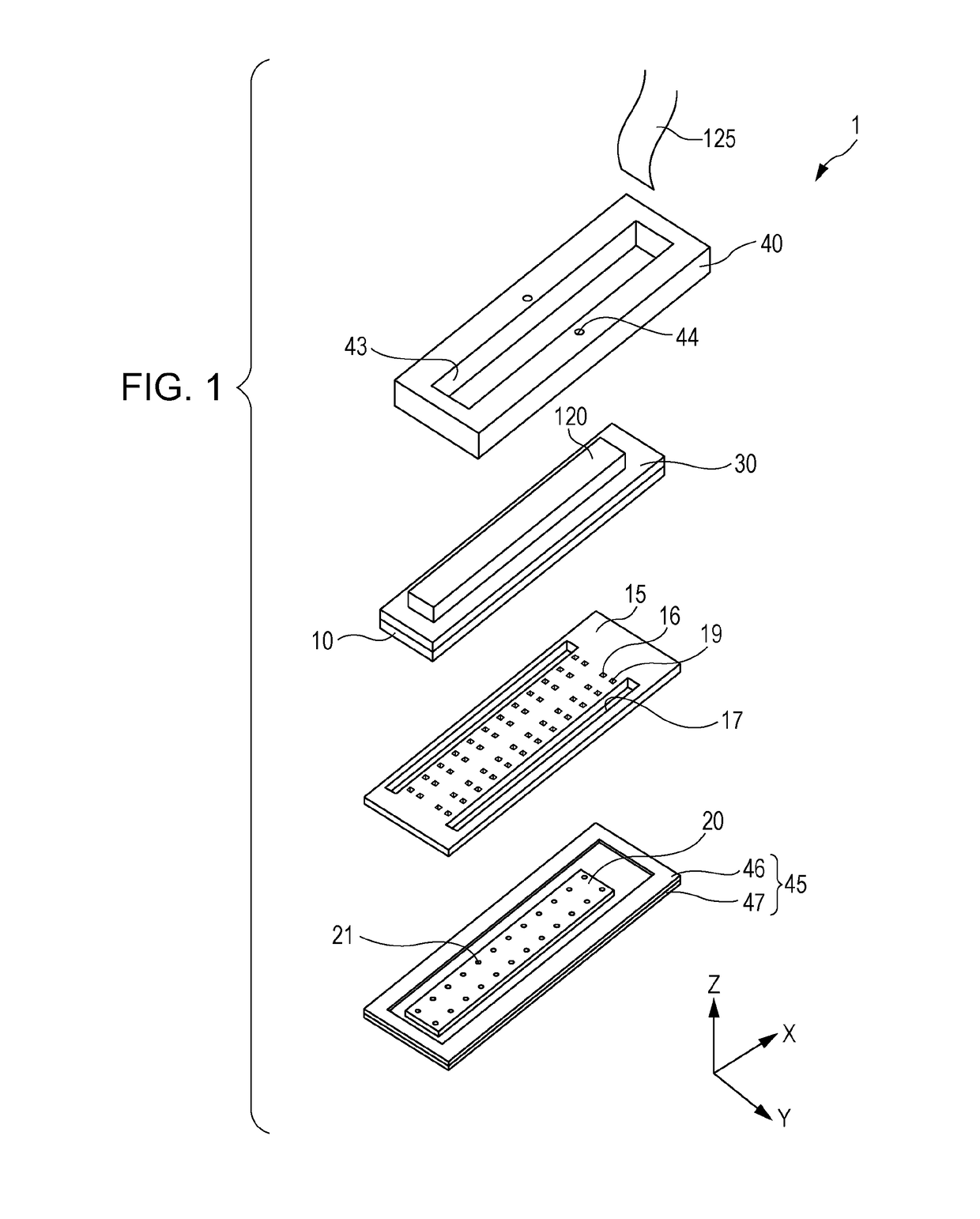
[0032]An embodiment of the invention will be described in detail. In the embodiment, an ink jet recording head that ejects ink as an example of a liquid ejecting head (hereinafter, simply refer to as a recording head) will be described.

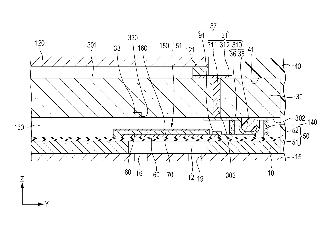
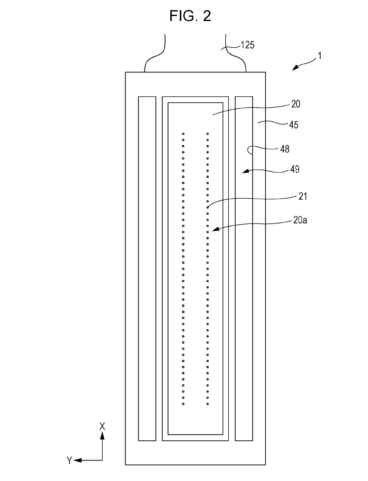
[0033]FIG. 1 is an exploded perspective view of a recording head, FIG. 2 is a plan view of the recording head, FIG. 3 is a plan view of a flow path forming substrate of the recording head, FIG. 4 is a bottom view of a wiring substrate of the recording head, FIG. 5 is a plan view of the wiring substrate of the recording head, FIG. 6 is a cross-sectional view taken along line VI-VI of FIG. 3, FIG. 7 is an enlarged view of FIG. 6, FIG. 8 is a cross-sectional view taken along line VIII-VIII of FIG. 3, and FIG. 9 is an enlarged view of FIG. 8. FIG. 2 and FIG. 4 are plan views of a lower surface side (liquid ejecting surface 20a side) of the recording head 1, FIG. 3 and FIG. 5 are plan views of an upper surface side (case member 40 side) of the recording he...

second embodiment

[0126]In the recording head 1 of the first embodiment, the first common wirings 92 are disposed outside the plurality of first individual wirings 91 disposed on the flow path forming substrate 10 along the first direction X (refer to FIG. 3), but it is not limited to such an aspect. The first common wiring 92 may be disposed between the first individual wirings 91.

[0127]FIG. 10 is a plan view of the flow path forming substrate, and FIG. 11 is a bottom view of the wiring substrate. The same reference numerals are given to the same components as those in the first embodiment, and redundant descriptions will be omitted.

[0128]As illustrated in FIG. 10, the first common wiring 92A is disposed at a ratio of one for the plurality of first individual wirings 91 in each of the piezoelectric element rows 150A on the flow path forming substrate 10, and the first common wirings 92A thereof are disposed between the first individual wirings 91. In the embodiment, one first common wiring 92A is di...


PUM


Abstract

A piezoelectric device includes an actuator substrate that includes a plurality of piezoelectric element rows having a plurality of piezoelectric elements, and a wiring substrate that is disposed so as to face the actuator substrate. The piezoelectric element rows include a plurality of individual electrodes disposed for each of the piezoelectric elements, and a common electrodes common to the plurality of piezoelectric elements. The wiring substrate includes a core portion disposed on a surface on the actuator substrate side, an individual wiring portion that partially covers the core portion, a common wiring portion that partially covers the core portion, and an auxiliary wiring disposed in a groove portion disposed on a first principal surface on the side opposite to the actuator substrate or on a second principal surface on the actuator substrate side. The auxiliary wiring is electrically connected to the common wiring portion. The individual electrode and the common electrode are respectively electrically connected to the individual wiring portion and the common wiring portion.

Description

[0001]The entire disclosure of Japanese Patent Application No: 2016-054397, filed Mar. 17, 2016 is expressly incorporated by reference herein in its entirety.BACKGROUND1. Technical Field[0002]The present invention relates to a piezoelectric device, a liquid ejecting head, and a liquid ejecting apparatus.2. Related Art[0003]A representative example of a liquid ejecting head that ejects liquid droplets includes an ink jet recording head that ejects ink droplets. As the ink jet recording head, for example, there is known a device that includes a flow path forming substrate in which a pressure generating chamber communicating with a nozzle opening is formed, and a piezoelectric element disposed on one side of the flow path forming substrate, and in which ink droplets are ejected from the nozzle opening by causing a pressure change in ink in the pressure generating chamber by a piezoelectric element.[0004]A wiring substrate is disposed so as to face the flow path forming substrate, and w...

Claims


Application Information

Patent Timeline
Patent Type & Authority Patents(United States)
IPC IPC(8): B41J2/14
CPCB41J2/14233B41J2002/14362B41J2002/14491B41J2202/13B41J2202/20
Inventor HIRAI, EIJUTAKABE, MOTOKITSUKAHARA, KATSUTOMONAGANUMA, YOICHISAIMEN, MUNEHIDE
Owner SEIKO EPSON CORP
Why Eureka
Try Eureka