Regulator circuit

a technology of regulator circuit and output voltage, applied in the direction of electric variable regulation, process and machine control, instruments, etc., can solve the problem of significant drop in output voltage, and achieve the effect of suppressing the drop in output voltag

Active Publication Date: 2019-09-17
PANASONIC SEMICON SOLUTIONS CO LTD
View PDF16 Cites 0 Cited by
  • Summary
  • Abstract
  • Description
  • Claims
  • Application Information

AI Technical Summary

Benefits of technology

[0009]In the regulator circuit according to one aspect of the present disclosure, it is possible to suppress the output voltage variation relative to the change in the load current, and also suppress the drop in the output voltage even when the load current is large.

Problems solved by technology

However, in the conventional regulator circuit disclosed in U.S. Pat. No. 8,378,654, there is a problem in that because the constant output bias current flows independent of the load current, when the load current is large, the output voltage drops significantly as compared with when the output bias current is not allowed to flow.

Method used


Image

  • Regulator circuit
  • Regulator circuit
  • Regulator circuit

Examples


embodiment 1

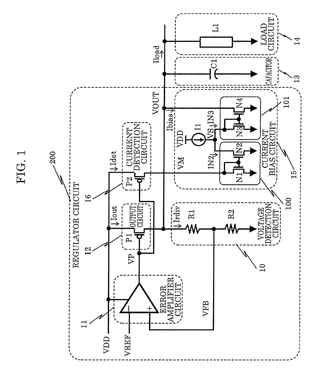
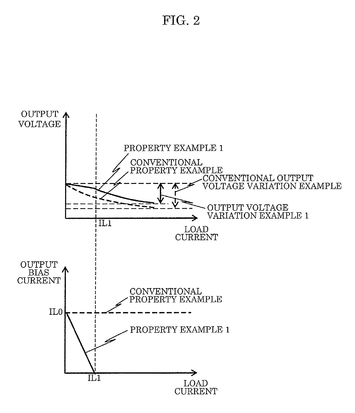
[0037]FIG. 1 is a diagram showing a configuration example of regulator circuit 200 according to Embodiment 1, and peripheral circuits of the regular circuit.

[0038]Regulator circuit 200 shown in the diagram includes voltage detection circuit 10, error amplifier circuit 11, output circuit 12, current bias circuit 15, and current detection circuit 16. Also, in the diagram, capacitor 13 and load circuit 14 are shown as peripheral circuits. Capacitor 13 is composed of capacitor C1, and is provided in order to suppress AC variation of output node VOUT. Load circuit 14 is composed of load circuit L1, and load current Iload flows in a direction in which it flows from output node VOUT.

[0039]Regulator circuit 200 includes: voltage detection circuit 10 that outputs feedback voltage VFB according to output voltage VOUT of output node VOUT; error amplifier circuit 11 that outputs voltage VP that is a result of comparison between feedback voltage VFB of voltage detection circuit 10 and reference ...

embodiment 2

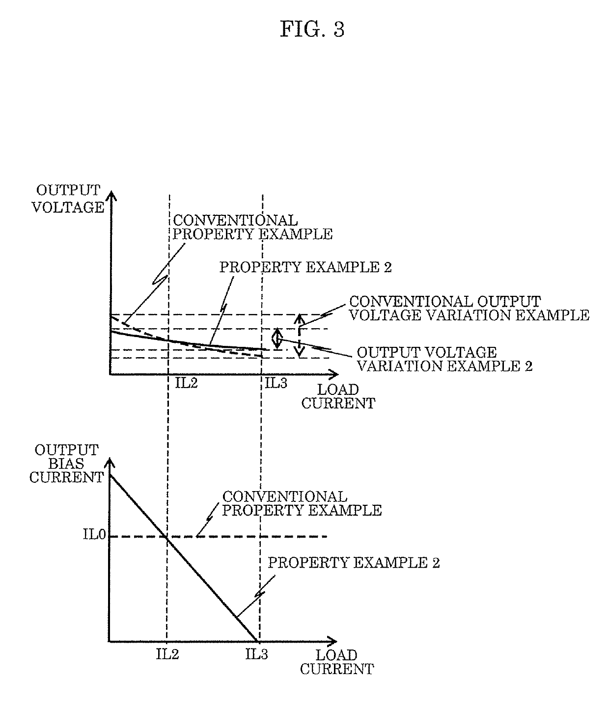
[0089]FIG. 4 is a diagram showing a configuration example of regulator circuit 200 according to Embodiment 2, and peripheral circuits of the regular circuit. In FIG. 4, structural elements that have the same functions as those of regulator circuit 200 according to Embodiment 1 described above are given the same reference numerals, and a detailed description thereof is omitted. Only differences will be described here.

[0090]Regulator circuit 200 shown in FIG. 4 has the same configuration as that of regulator circuit 200 shown in FIG. 1, except that current bias circuit 15 of regulator circuit 200 shown in FIG. 1 has been replaced by current bias circuit 15 shown in FIG. 4.

[0091]Current bias circuit 15 according to Embodiment 2 is composed of second current source I2 and third current mirror 102. Current bias circuit 15 includes an input terminal that is connected to node VM that is the output terminal of current detection circuit 16, and an output terminal that is connected to output ...

embodiment 3

[0115]FIG. 5 is a diagram showing a configuration example of regulator circuit 200 according to Embodiment 3, and peripheral circuits of the regular circuit. In FIG. 5, structural elements that have the same functions as those of regulator circuit 200 according to Embodiment 2 described above are given the same reference numerals, and a detailed description thereof is omitted. Only differences will be described here.

[0116]Regulator circuit 200 shown in FIG. 5 has the same configuration as that of regulator circuit 200 shown in FIG. 4, except that current bias circuit 15 of regulator circuit 200 shown in FIG. 4 has been replaced by current bias circuit 15 shown in FIG. 5.

[0117]Current bias circuit 15 according to Embodiment 3 is composed of second current source I2, third current mirror 102, and clamp circuit 17, and has a configuration in which clamp circuit 17 is further included in current bias circuit 15 according to Embodiment 2. Current bias circuit 15 includes an input termina...


PUM


Abstract

A regulator circuit includes: a voltage detection circuit that detects a magnitude of an output voltage of an output node, and outputs a feedback voltage that indicates a result of the detection; an error amplifier circuit that compares the feedback voltage with a reference voltage, and outputs a voltage that indicates a result of the comparison; an output circuit that supplies an output current to the output node according to the voltage output by the error amplifier circuit; a current detection circuit that detects a magnitude of the output current; and a current bias circuit that supplies an output bias current to the output node, and increases or decreases the output bias current based on a result of the detection of the current detection circuit.

Description

CROSS REFERENCE TO RELATED APPLICATIONS[0001]This application is a U.S. continuation application of PCT International Patent Application Number PCT / JP2017 / 011308 filed on Mar. 22, 2017, claiming the benefit of priority of Japanese Patent Application Number 2016-061681 filed on Mar. 25, 2016, the entire contents of which are hereby incorporated by reference.BACKGROUND1. Technical Field[0002]The present disclosure relates to a regulator circuit.2. Description of the Related Art[0003]A conventional regulator circuit will be described. FIG. 12A is a diagram showing a configuration of a conventional regulator circuit disclosed in U.S. Pat. No. 8,378,654. PMOS transistor 202 in an output stage of the regulator circuit supplies a sufficient electric current to a load. Bias voltage VBIAS causes NMOS transistor 204 to operate in a saturation region, independent of the environment.[0004]FIG. 12B is a diagram showing the properties of the output voltage with respect to the load current of the ...

Claims


Application Information

Patent Timeline
Patent Type & Authority Patents(United States)
IPC IPC(8): G05F1/565G05F1/56G05F1/575G05F1/59
CPCG05F1/59G05F1/56G05F1/575G05F1/565
Inventor ONO, TAKASHIMOCHIDA, REIJI
Owner PANASONIC SEMICON SOLUTIONS CO LTD
Why Eureka
Try Eureka