Switching power supply

a power supply and switching technology, applied in the direction of electric variable regulation, process and machine control, instruments, etc., can solve the problems of large transient drop in output voltage, constant power loss, and inability to achieve, so as to suppress the drop in direct current output voltage and reduce power consumption

Active Publication Date: 2015-05-26
FUJI ELECTRIC CO LTD
View PDF7 Cites 0 Cited by
  • Summary
  • Abstract
  • Description
  • Claims
  • Application Information

AI Technical Summary

Benefits of technology

[0010]Consequently, an object of the invention is to provide a switching power supply that, being a flyback type switching power supply that acquires output voltage information using a tertiary winding and controls an output voltage to a constant voltage, can suppress a drop in the output voltage due to a sudden load change when there is a light load or no load in a circuit wherein power consumption is normally low.
[0016]According to the invention, a flyback type switching power supply, which detects a tertiary winding voltage and controls an output voltage to a constant voltage, detects a sudden load change using a differentiating circuit, which normally has no power consumption, that detects only a transient fluctuation of a direct current output voltage, and starts the switching of a primary side semiconductor switch when there is no load or a light load, even when the semiconductor switch is in an off state, thereby enabling the detection of the direct current output voltage in a tertiary winding and suppressing a drop in the direct current output voltage. As a result of this, it is possible to reduce power consumption and to suppress the drop in the direct current output voltage when there is the sudden load change.

Problems solved by technology

However, although it is possible to realize a stable control by directly detecting a secondary side voltage, a power loss constantly occurs in the voltage detector circuit that uses the photo-coupler, which is an impediment to energy saving and increased efficiency.
Because of this, when a sudden load change occurs in a state in which the switching frequency is lowered, and power consumption reduced, when there is a light load or no load, it is not possible, even when the output voltage drops due to the sudden load change, to detect the drop in the output voltage until the next switching.
When the switching frequency is lower when there is a light load or no load, the interval between switchings is longer, meaning that there is a problem in that there is a transient large drop in the output voltage between the sudden load change occurring and the next switching.

Method used


Image

  • Switching power supply
  • Switching power supply
  • Switching power supply

Examples


first embodiment

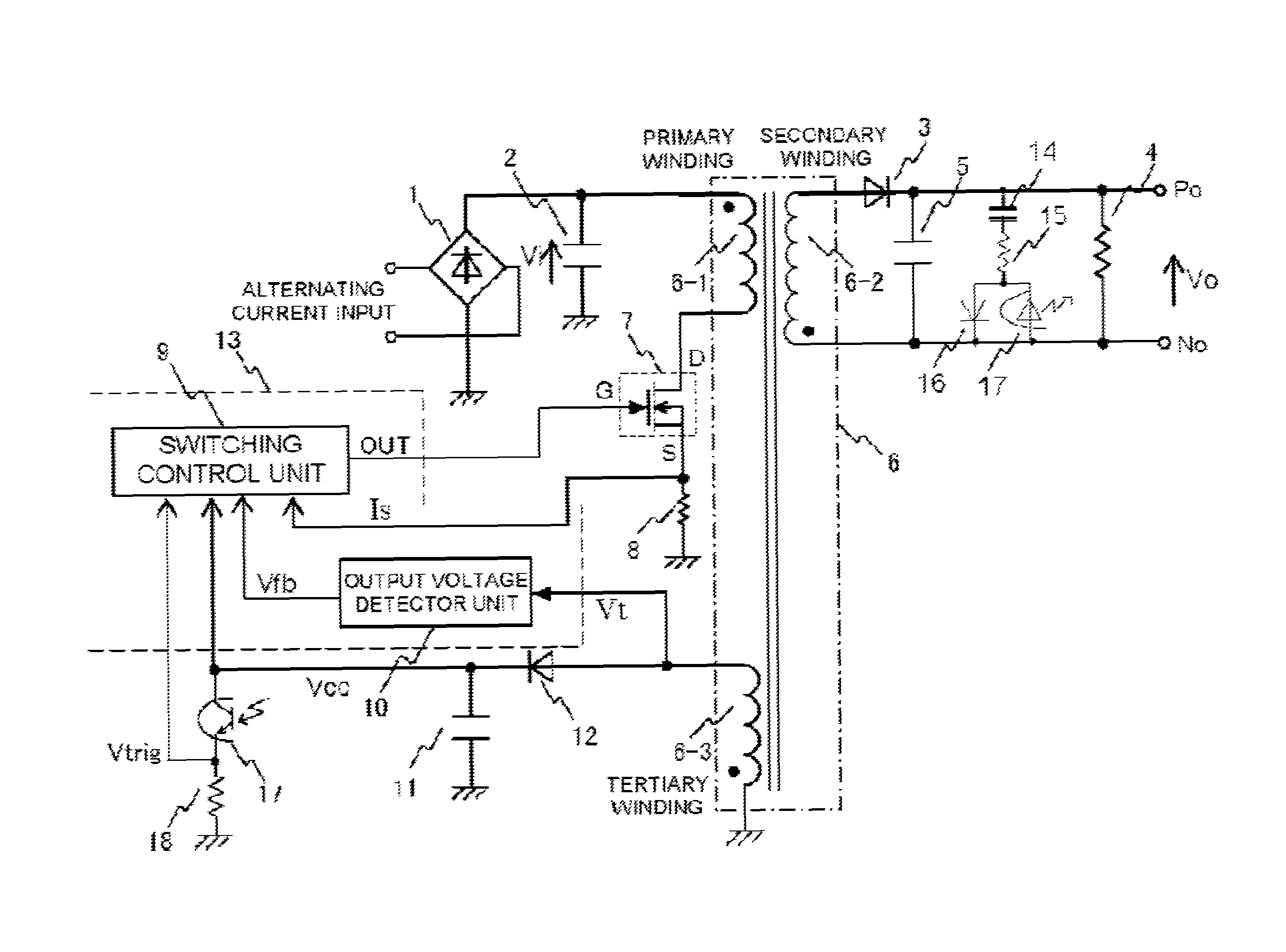
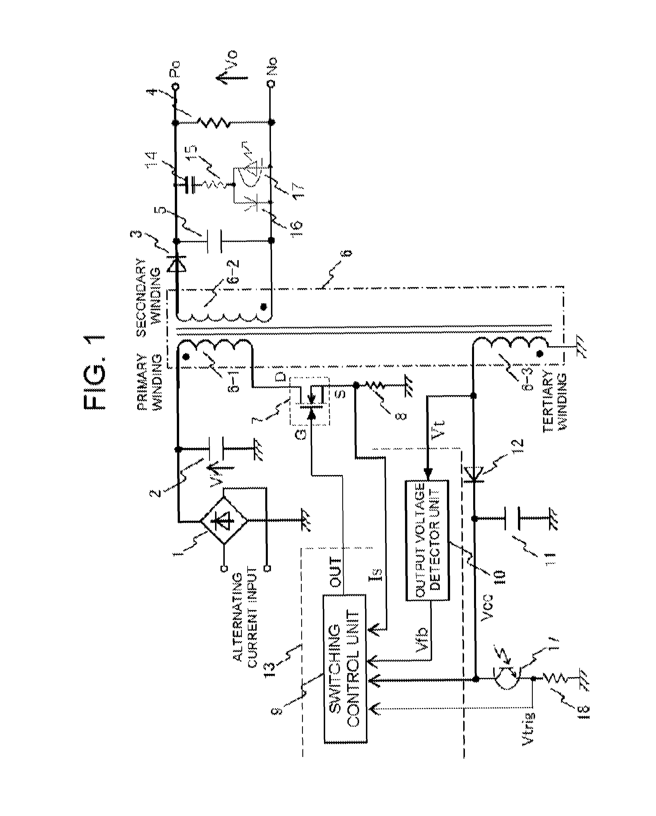
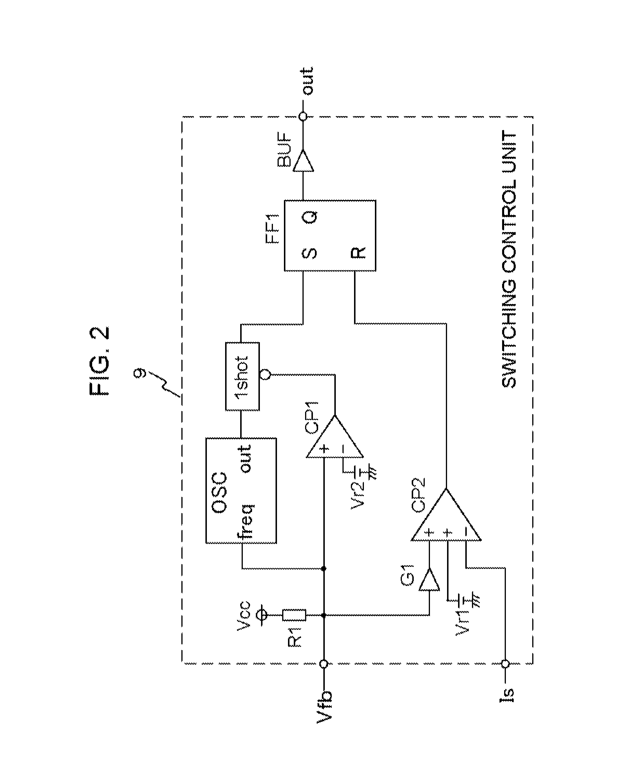
[0031]FIG. 1 shows an overall circuit of embodiments of the invention, FIG. 2 a detailed circuit of a switching control unit 9, FIG. 3 a first embodiment of the invention, and FIG. 4 operating waveforms.

[0032]FIG. 1 is an overall circuit example of a main circuit configuration of a switching power supply of the invention. In the drawing, a transformer 6 has a primary winding 6-1 into which a direct current input voltage Vin is input, a secondary winding 6-2 for outputting an output voltage Vo, and a tertiary winding 6-3 for generating a power source voltage Vcc of a control circuit 13 at the same time as detecting a voltage generated in the secondary winding 6-2. As the polarities of the primary winding 6-1 and the secondary winding 6-2 are mutually opposite, the switching power supply of the invention is a flyback type. A diode 3, a rectifying and smoothing circuit formed of a capacitor 5, and a dummy resistor 4 for suppressing the rise of the output voltage when there is a light l...

second embodiment

[0038]FIG. 5 shows a second embodiment of the invention, and FIG. 6 shows operating waveforms. The first embodiment of the invention is a configuration wherein a trigger signal for the semiconductor switch is compiled (e.g., caused or generated) by a signal from the sudden load change detector circuit, but the second embodiment of the invention is a configuration wherein a sudden load change signal detected by the series circuit of the phototransistor and the resistor 18 is input as a feedback signal into the switching control unit 9, thereby increasing the switching frequency of a gate signal for the semiconductor switch 7. The relationship between the feedback voltage Vfb and a switching frequency Fsw is shown in FIG. 7. It can be seen that when the feedback voltage Vfb is increased, the switching frequency Fsw increases. As the frequency when there is a light load or no load is low when the switching frequency is increased, switching is started immediately, even when the semicond...


PUM


Abstract

A flyback type switching power supply includes between P and N of a direct current output a sudden load change detector circuit, which normally has no power consumption, that detects only a transient fluctuation of a direct current output voltage, and starts the switching of a primary side semiconductor switch when there is no load or a light load, even when the semiconductor switch is in an off state, thereby enabling the detection of the direct current output voltage in a tertiary winding, and suppressing a drop in the direct current output voltage.

Description

CROSS-REFERENCE TO RELATED APPLICATION[0001]This application claims priority under 35 U.S.C. §119 from Japanese Patent Application No. 2011-263318, filed on Dec. 1, 2011, the entirety of which is incorporated herein by reference.BACKGROUND OF THE INVENTION[0002]1. Technical Field[0003]The present invention relates to a flyback type switching power supply that produces a second direct current voltage isolated by a transformer from a first direct current power source with a switching operation of a semiconductor switch, and in particular, relates to a control circuit that detects a transformer secondary side output voltage using an auxiliary winding (tertiary winding), and controls the output voltage to a constant voltage.[0004]2. Related Art[0005]A switching power supply is utilized as a power supply for a charger or a power supply of a notebook computer AC adaptor in order to supply a constant voltage to a load. As a heretofore known method, there is a method whereby a voltage detec...

Claims


Application Information

Patent Timeline
Patent Type & Authority Patents(United States)
IPC IPC(8): H02M3/335H02M1/00
CPCH02M3/33523H02M2001/0032Y02B70/16H02M1/0032Y02B70/10
Inventor SAKURAI, MASAHIKONISHIKAWA, YUKIHIRO
Owner FUJI ELECTRIC CO LTD
Why Eureka
Try Eureka