
Gas detecting system

Inactive Publication Date: 2005-07-28
NGK SPARK PLUG CO LTD
View PDF4 Cites 2 Cited by
  • Summary
  • Abstract
  • Description
  • Claims
  • Application Information

AI Technical Summary

Benefits of technology

[0022] If, therefore, the invention is applied to the gas detecting system having the heater unit, it is possible to exhibit the effect of the invention more for reducing the influences of the noise on the electric current to the leadwires. Specifically, if the gas detecting system is configured such at the two or more lead wires including at least the common lead wire have a portion to contact in the electrically insulated state, a prominent effect on the counter-measures against the noise can be obtained to suppress the drop of the gas detecting precision.
[0023] In the invention, moreover, the noise reduction is made by bringing the two or more lead wires including at least the common lead wire of the lead wires connected with the sensor element into contact with each other so that the detection precision of the internal resistance of the oxygen concentration measuring cell is also improved. As a result, the internal resistance of the oxygen concentration measuring cell can be precisely detected to control the calorific value (i.e., the value of the current fed to the heater unit) of the heater unit properly on the basis of that internal resistance.
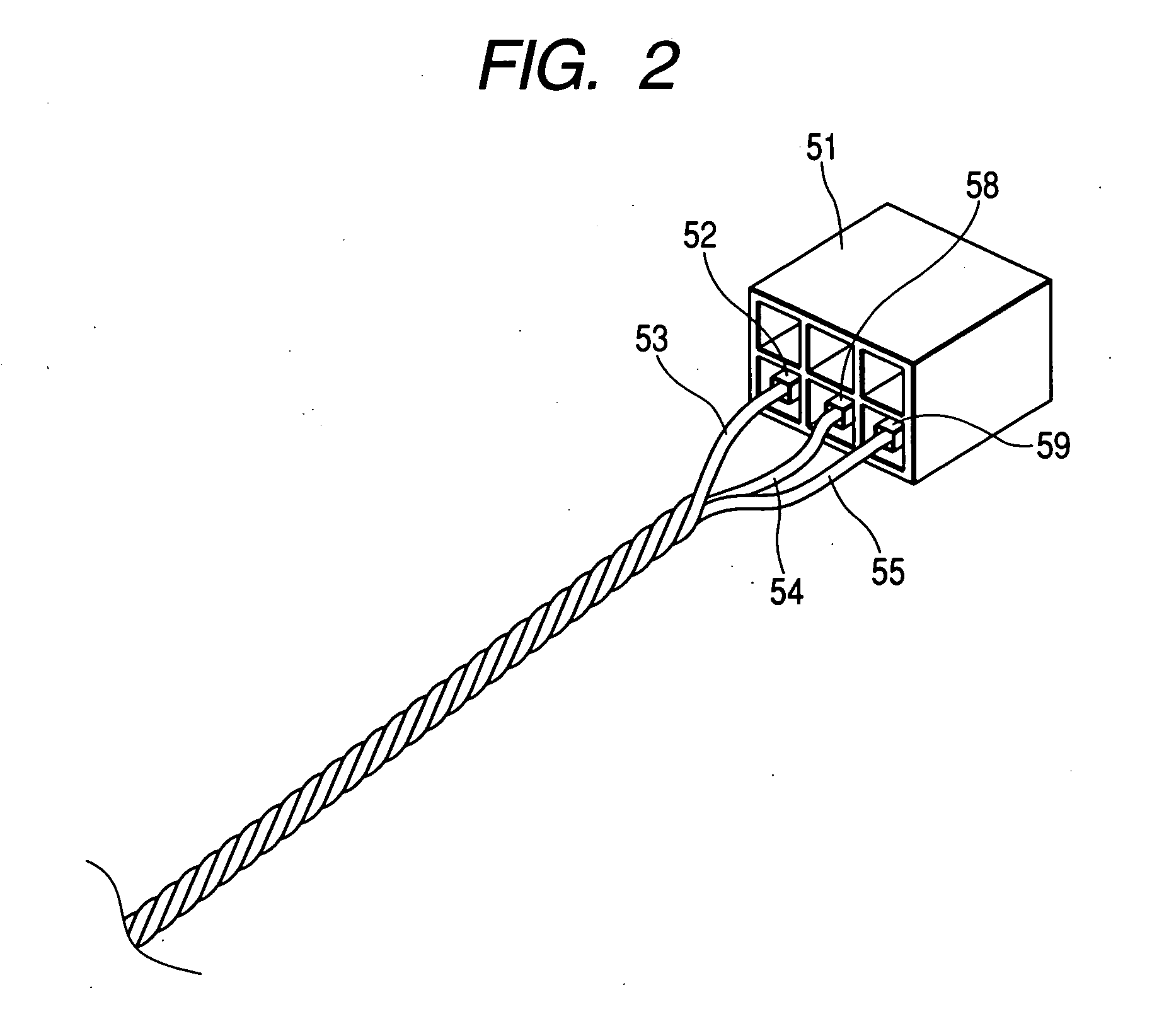
[0024] Next in the aforementioned gas detecting system, according to a third aspect of the invention, the gas detecting system may further comprises: a binding member that binds said plurality of lead wires, and the common lead wire is bound with at least one of the other lead wires by the binding member, so as to contact with the other lead wires.
[0025] When the plural lead wires are to be brought into contact with each other, they are bound by using the binding member so that the portion for at least the lead wires to contact can be formed to reduce the influences of the noise.
[0026] Here, the binding member can be exemplified by an adhesive tape or a binding band. By using a plurality of binding members to bind the plural lead wires at a constant interval, the areas for the contacting portions of the lead wires can be retained large to improve the noise reducing effect. The binding member can also be additionally exemplified by a glass tube or a corrugated tube.
[0027] In the aforementioned gas detecting system, according to a fourth aspect of the invention, said common lead wire may be bound in a twisted mode with at least one of the other lead wires, so as to contact with said remaining lead wires.

Problems solved by technology

However, the aforementioned shielded wires are more expensive than the general lead wires thereby to raise a problem that the gas detecting system configured with the shielded wires raises the price.
Under the influences of the noise, the electric signal to flow between the sensor element and the control unit fluctuates to raise another problem that the gas detecting precision drops.
Moreover, the use of the unshielded lead wires causes the influences of the noise to fluctuate the electric signal, which flows between the sensor element and the resistance detecting unit for detecting the internal resistance of the former.
This fluctuation raises a problem that the detection precision of the internal resistance drops.

Method used


Image

  • Gas detecting system
  • Gas detecting system
  • Gas detecting system

Examples


embodiment 1

(Embodiment 1)

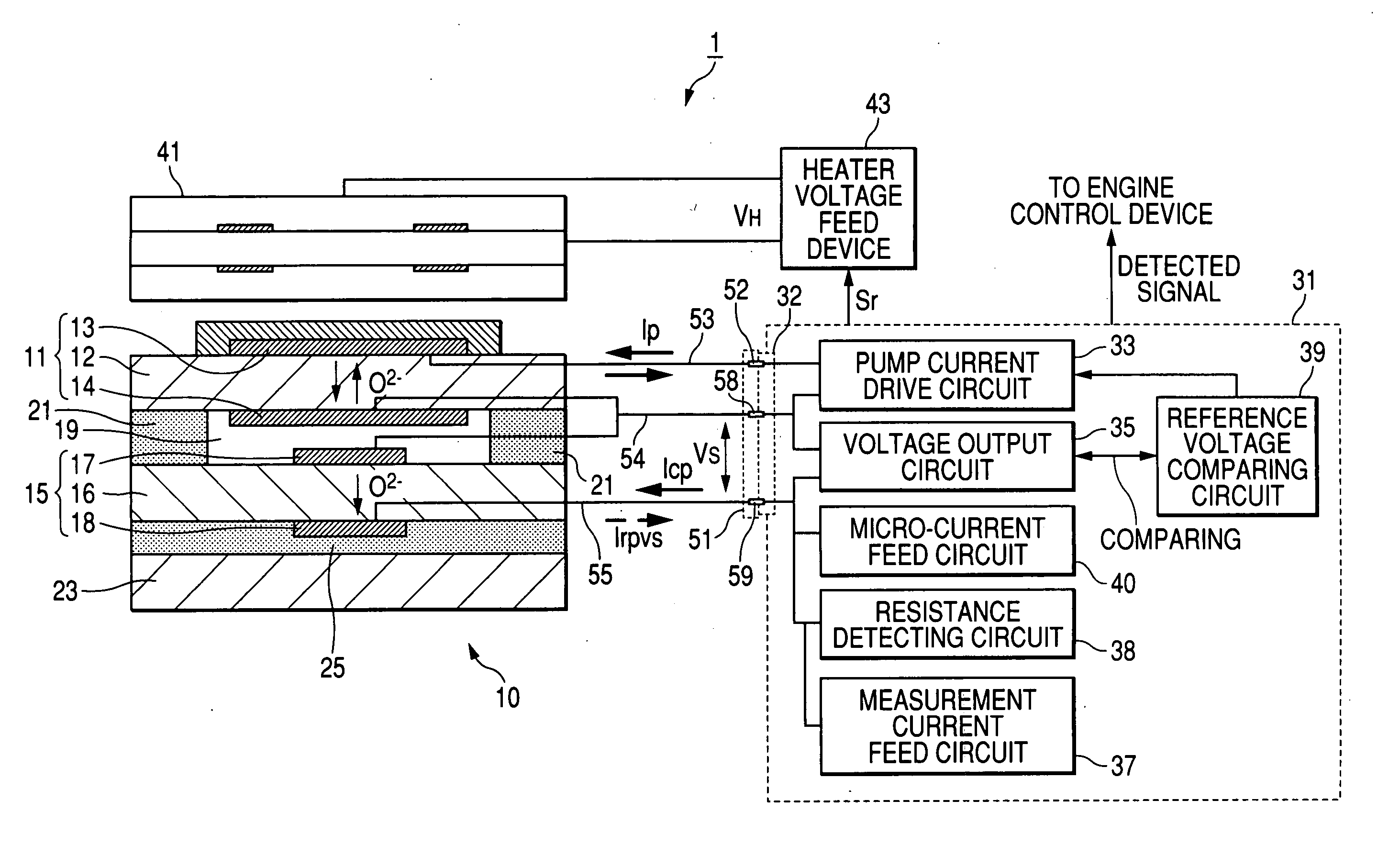
[0047] A gas detecting system 1 provided with a universal air / fuel ratio sensor will be described as Embodiment 1 according to the invention with reference to the accompanying drawings. The gas detecting system of Embodiment 1 detects the concentration of oxygen contained in the exhaust gas of an internal combustion engine, and the detection result of the oxygen concentration is used to control the air / fuel ratio of the internal combustion engine.

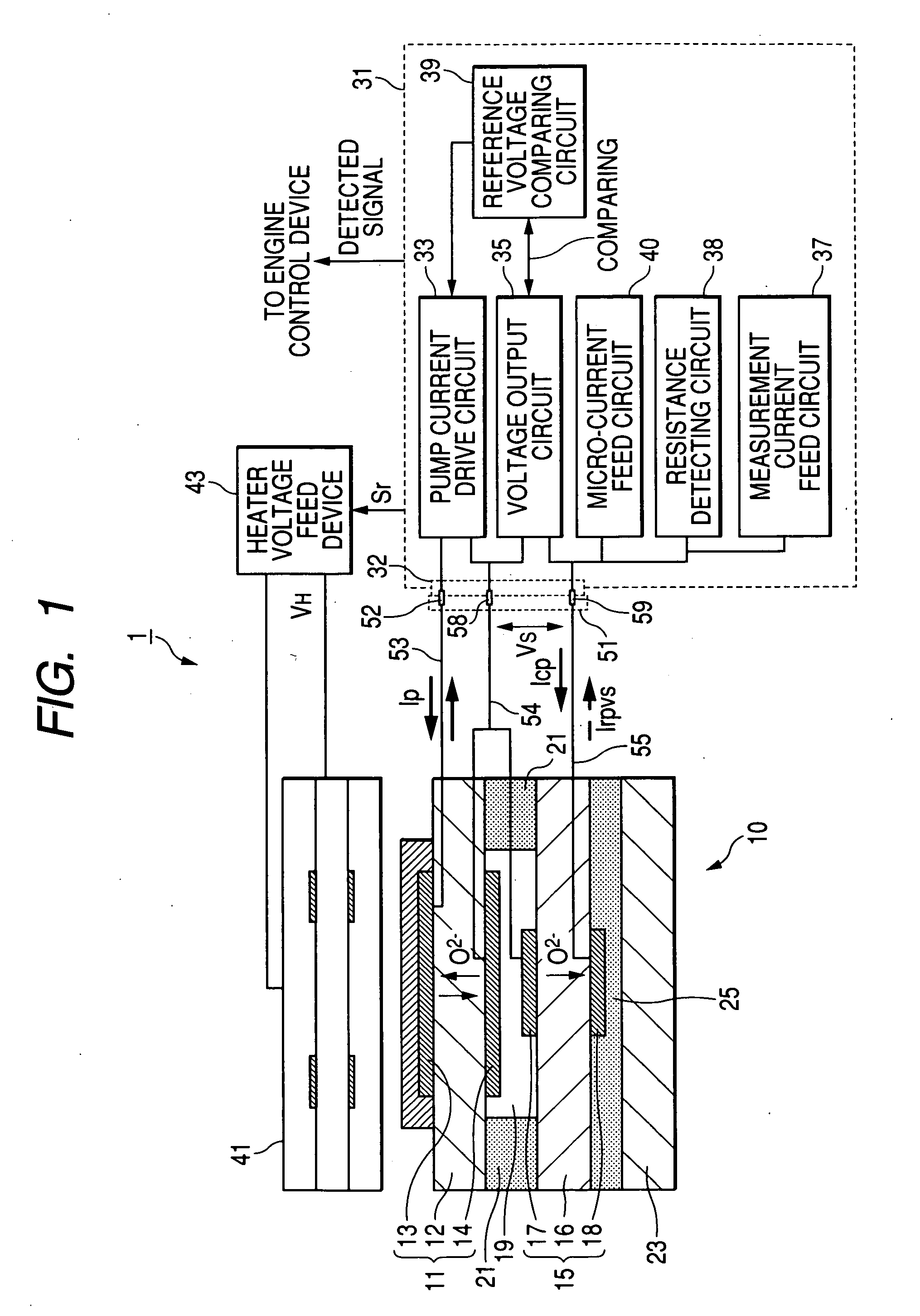
[0048]FIG. 1 is a system configuration diagram showing a schematic configuration of the gas detecting system

[0049] This gas detecting system 1 is configured to include: a universal air / fuel ratio sensor element 10; a sensor control circuit 31 connected with the universal air / fuel ratio sensor element 10; a ceramic heater 41 for heating the universal air / fuel ratio sensor element 10; and a heater voltage feed device 43 connected with the ceramic heater 41. Moreover, the gas detecting system 1 further includes three lead wires...

embodiment 2

(Embodiment 2)

[0090] Next, Embodiment 2 of the invention will be described on a gas detecting system 100, which is provided with a threshold current type air / fuel ratio sensor (as will be shortly called the “A / F sensor”) as the oxygen concentration sensor, with reference to the accompanying drawings. This gas detecting system of Embodiment 2 is also mounted on an internal combustion engine.

[0091] In FIG. 6, the gas detecting system 100 is provided with the A / F sensor, which outputs a linear air / fuel ratio detection signal according to the oxygen concentration in the exhaust gas as the voltage commanded by a microcomputer (as will be simply called the “micom”) 130 is applied. This micom is configured to include: a CPU or a central processing unit for executing a variety of well-known operations; a ROM stored with a control program; and a RAM for storing various data. A bias control circuit 140 and a heater control circuit 160 are controlled according to a predetermined control progr...


PUM


Abstract

A gas detecting system comprises: a sensor element including: an oxygen pump cell comprising a first oxygen ion conducting solid electrolyte layer between a first pair of electrodes; an oxygen concentration measuring cell comprising a second oxygen ion conducting solid electrolyte layer between a second pair of electrodes; and a measurement chamber between the oxygen pump cell and the oxygen concentration measurement cell; a plurality of lead wires connected with the first and second pairs of electrodes; and a control unit electrically connected with the electrodes through the lead wires, wherein the lead wires includes a common lead wire connected with electrodes confronting the measurement chamber of the first and second pairs of electrodes, and wherein the common lead wire has a portion to contact in an electrically insulated state with at least one of the lead wires other than the common lead wire.

Description

BACKGROUND OF THE INVENTION [0001] 1. Field of the Invention [0002] The present invention relates to a gas detecting system to be utilized for controlling the air / fuel ratio of an internal combustion engine for an automobile. Background Art [0003] 2. Description of the Related Art [0004] In the related art, a sensor element having an oxygen pump cell and an oxygen concentration measuring cell laminated one on the other is known as a sensor element for detecting a specific gas component in an objective gas to be measured. [0005] Here, the oxygen pump cell and the oxygen concentration measuring cell are formed by sandwiching an oxygen ion conducting solid electrolyte layer between a pair of electrodes, and the sensor element is configured by forming such a hollow measurement chamber between the oxygen pump cell and the oxygen concentration measuring cell as introduces the objective gas thereinto. [0006] There is known the gas detecting system (as referred to JP-A-10-048180, JP-A-10-14...

Claims


Application Information

Patent Timeline
IPC IPC(8): G01N27/407
CPCG01N27/407G01N27/4062
Inventor INOUE, YOSHINORIIEDA, NORIKAZUTANAKA, MASAHIROINAGAKI, HIROSHI
Owner NGK SPARK PLUG CO LTD
Learn More