
Plasma display panel driving method

a technology of plasma display panel and driving method, which is applied in the direction of gas discharge electrodes, gas discharge vessels/containers, instruments, etc., can solve the problems of deteriorating image quality, display quality drop, display quality drop, etc., to suppress the drop in the contrast of dark room, high display quality, and stable generation

Inactive Publication Date: 2011-05-10
PANASONIC CORP
View PDF7 Cites 0 Cited by
  • Summary
  • Abstract
  • Description
  • Claims
  • Application Information

AI Technical Summary

Benefits of technology

"The present invention provides a plasma display panel driving method that can stably generate a desired wall charge distribution in discharge cells, and suppress a drop in dark room contrast. The method includes a step of dividing a display period in each field of an input video signal into a plurality of subfield periods, and selectively generating an address discharge in the discharge cells by sequentially applying a scanning pulse, on which a positive polarity or a negative polarity base voltage is superimposed. The method also includes a step of decreasing the applied voltage in steps when a final applied pulse falls, and then decreasing the applied voltage toward a predetermined voltage having a different polarity. The driving method can improve the grayscale representation capability of the plasma display panel."

Problems solved by technology

In a conventional plasma display, it is difficult to control the wall charge distribution in the discharge cells.
For example, an unexpected discharge error may occur in the discharge cells, or a desired wall charge distribution may not be acquired due to a failure in erasing the wall charges, and therefore display quality may drop.
Also in some cases, a wall charge distribution, to be generated according to the address discharge, becomes unstable due to temperature fluctuation and age related deterioration of the display panel, which causes a dispersion in the intensity of a sustaining discharge in the discharge cells, and deteriorates the image quality.

Method used


Image

  • Plasma display panel driving method
  • Plasma display panel driving method
  • Plasma display panel driving method

Examples


first embodiment

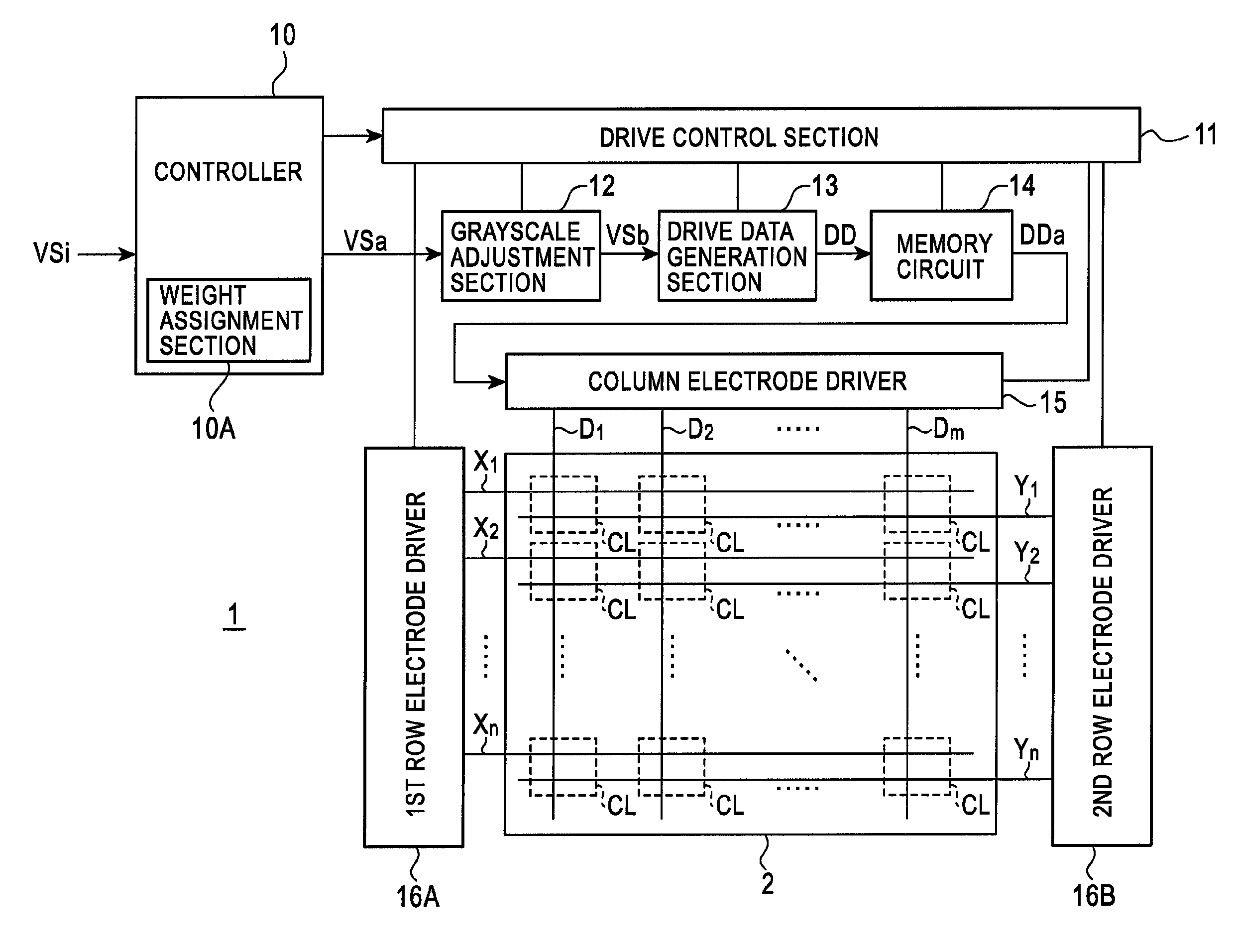
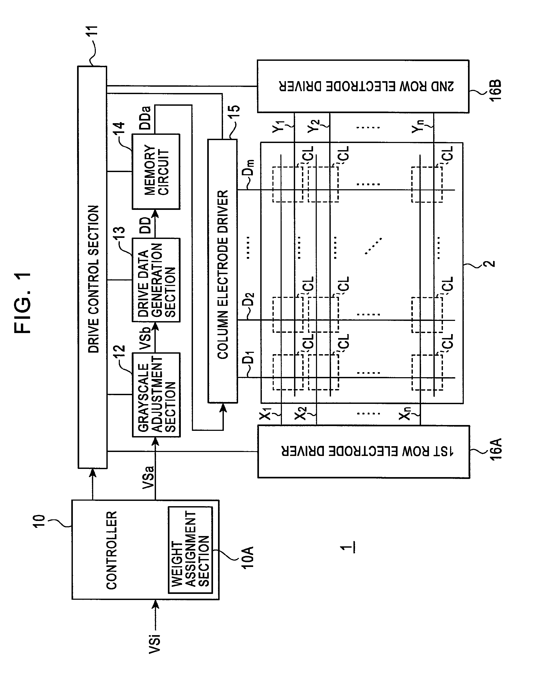
[0071]FIG. 13 is a diagram depicting a driving sequence according to a first embodiment of the present invention. In this driving sequence, one field of a video signal is divided into N number (N is 2 or greater integer) of subfields SF1, . . . , SFN, which are arrayed continuously in the display sequence. The plasma display device 1 displays these subfields SF1, . . . , SFN sequentially on the plasma display panel 2 whereby human eyes can recognize one multi-grayscale image. FIG. 14 is a timing chart depicting waveforms of driving signals according to the driving sequence in FIG. 13. FIG. 14 shows a signal waveform which is applied to the column electrodes D1 to Dn, a signal waveform which is applied to the common electrodes X1 to Xn, and a signal waveform which is applied to the scanning electrodes Y1, . . . , Yn respectively.

[0072]FIG. 15 is a diagram depicting an emission pattern of each discharge cell CL which can be implemented by the driving sequence in FIG. 13 and the conver...

second embodiment

[0107]Now a driving sequence according to a second embodiment of the present invention will be described. FIG. 21 is a diagram depicting the driving sequence according to the second embodiment. In this driving sequence, one field of a video signal is divided into N number (N is 2 or greater integer) of subfields SF1, . . . , SFN, which are arrayed continuously in the display sequence. The plasma display device 1 displays these subfields SF1, . . . , SFN sequentially on the plasma display panel 2, whereby human eyes can recognize one multi-grayscale image. FIG. 22 is a timing chart depicting waveforms of driving signals according to the driving sequence in FIG. 21. FIG. 21 shows a signal waveform which is applied to the column electrodes D1 to Dn, a signal waveform which is applied to the common electrodes X1 to Xn, and a signal waveform which is applied to the scanning electrodes Y1, . . . , Yn respectively.

[0108]As FIG. 21 shows, in the display period of the first subfield SF1, a r...

third embodiment

[0120]Now a driving sequence according to a third embodiment of the present invention will be described. FIG. 23 is a diagram depicting the driving sequence according to the third embodiment. In this driving sequence, one field of a video signal is divided into N number (N is 2 or greater integer) of subfields SF1, . . . , SFN, which are arrayed continuously in the display sequence. The plasma display device 1 displays these subfields SF1, . . . , SFN sequentially on the plasma display panel 2, whereby human eyes can recognize one multi-grayscale image. FIG. 24 is a timing chart depicting waveforms of driving signals according to the driving sequence in FIG. 23. FIG. 24 shows a signal waveform which is applied to the column electrodes D1 to Dn, a signal waveform which is applied to the common electrodes X1 to Xn, and a signal waveform which is applied to the scanning electrodes Y1, . . . , Yn respectively.

[0121]FIG. 25 is a diagram depicting an emission pattern of each discharge cel...


PUM


Abstract

A driving method includes generating an address discharge in selected cells out of discharge cells and setting the selected cells to either an emission enable state or a non-emission state in an address period which is set in each subfield period. The driving method also includes generating sustaining discharge in discharge cells being set to the emission enable state by applying at least one discharge sustaining pulse P+ between a scanning electrode and a common electrode constituting each row electrode pair, in a discharge sustaining period following the address period. The driving method also includes decreasing the applied voltage between the scanning electrode and common electrode in steps when a final applied pulse P+ out of the discharge sustaining pulses falls.

Description

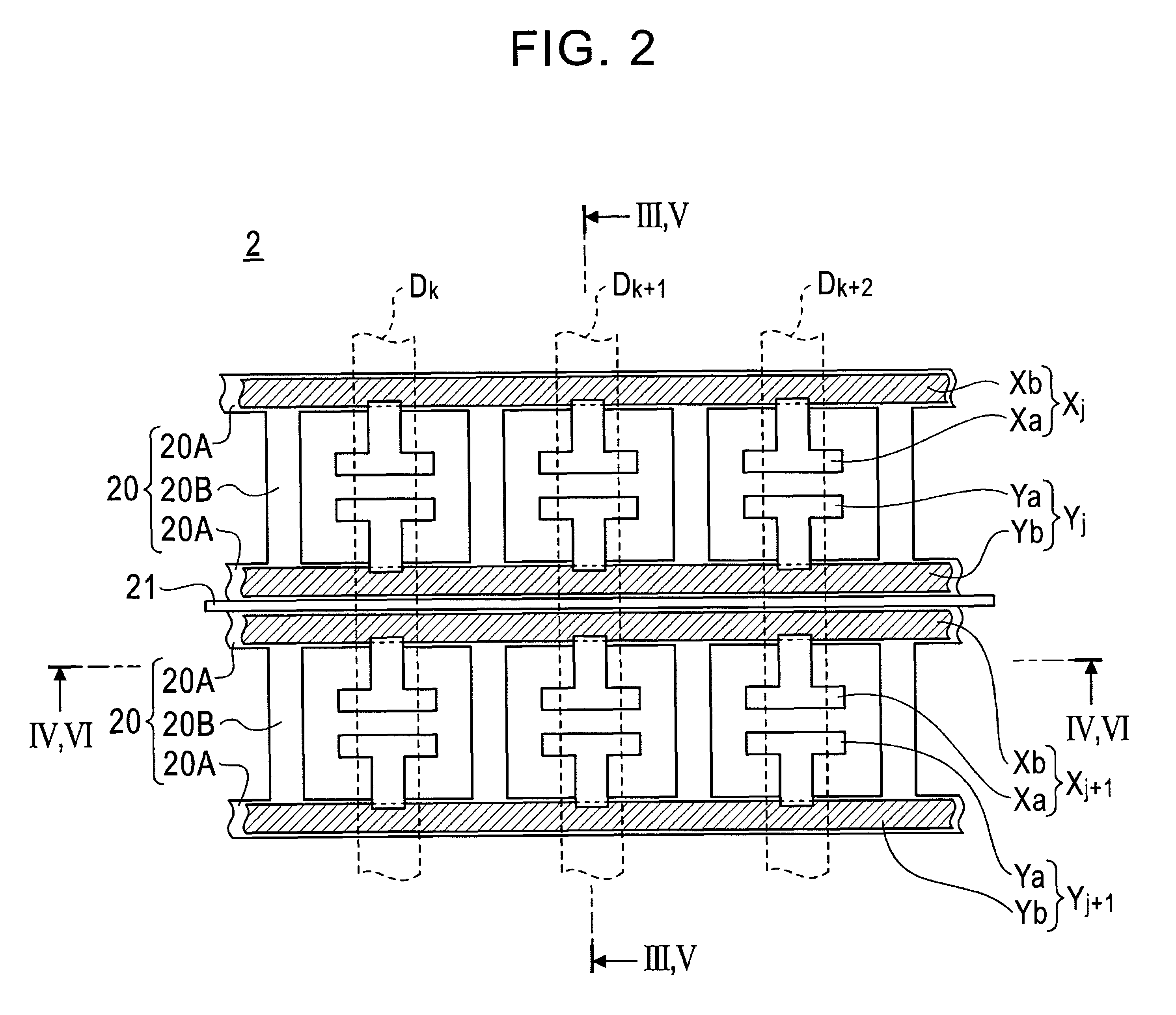
BACKGROUND OF THE INVENTION[0001]1. Field of the Invention[0002]The present invention relates to a driving technology for a plasma display panel, which divides each field of a video signal into a plurality of subfields, and displays multi-grayscale images by a combination of the subfields.[0003]2. Description of the Related Art[0004]A plasma display has a display panel having a plurality of discharge cells, in which a fluorescent layer is coated respectively, and which are arrayed in a matrix. Generally a display panel has a plurality of row electrode pairs which are formed on a substrate, a plurality of column electrodes which are formed facing the row electrode pairs, and a plurality of discharge cells formed at areas where the row electrode pairs and the column electrodes cross respectively. These discharge cells are arranged in a matrix, and a fluorescent layer is coated inside each discharge cell. In a plasma display, a gas discharge for initially adjusting the charge distribut...

Claims


Application Information

Patent Timeline
Patent Type & Authority Patents(United States)
IPC IPC(8): G09G3/28G09G3/292G09G3/20G09G3/288G09G3/291G09G3/293G09G3/294G09G3/298H01J11/22H01J11/24H01J11/34H01J11/42
CPCG09G3/2927G09G3/2932G09G3/2935G09G3/2022G09G2320/0271G09G2320/0228G09G2320/0238
Inventor MASHITA, TAKASHIHOMMA, HAJIME
Owner PANASONIC CORP
Learn More