DC-DC converter control circuit and control method

a control circuit and converter technology, applied in the direction of dc-dc conversion, power conversion systems, instruments, etc., can solve the problems of difficult to choose an optimum switching frequency, and achieve the effect of suppressing the drop in the output voltage of dc-dc converters

Active Publication Date: 2014-11-04
FUJI ELECTRIC CO LTD
View PDF6 Cites 0 Cited by
  • Summary
  • Abstract
  • Description
  • Claims
  • Application Information

AI Technical Summary

Benefits of technology

[0008]Therefore, the invention has an object of providing a DC-DC converter control circuit and control method that reduce the amount of a drop in output voltage when a load current increases suddenly by driving a switch by switching from a fixed frequency PWM control of a switching element to a control whereby an ON time is set before and after a predetermined OFF time.
[0013]According to the invention, when it is detected that the output voltage of a DC-DC converter has dropped below a predetermined value, a switch is driven by switching from a fixed frequency PWM control based on the output voltage of an error amplifier to a control whereby an ON time determined based on the output voltage of the error amplifier is set before and after a predetermined OFF time, meaning that it is possible to suppress a drop in the output voltage of the DC-DC converter.

Problems solved by technology

However, as an ON time period at a point at which an output voltage fluctuation occurs varies depending on operating conditions, and also changes during a transient response, it is difficult to choose an optimum switching frequency for all conditions with the method disclosed in JP-A-2010-022186 (while the effect is insufficient when a switching cycle is too long in comparison with the ON time period, the ON condition continues when the switching cycle is shorter than the ON time period).

Method used


Image

  • DC-DC converter control circuit and control method
  • DC-DC converter control circuit and control method
  • DC-DC converter control circuit and control method

Examples


embodiment

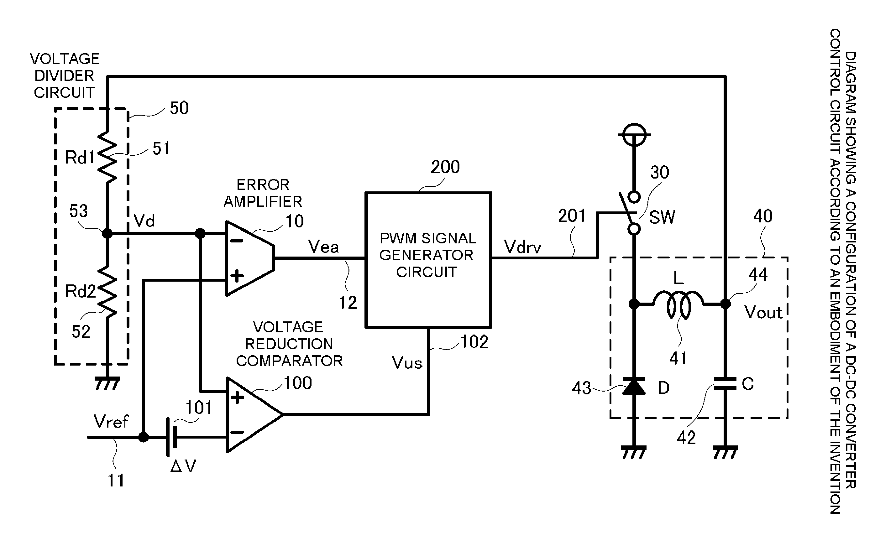
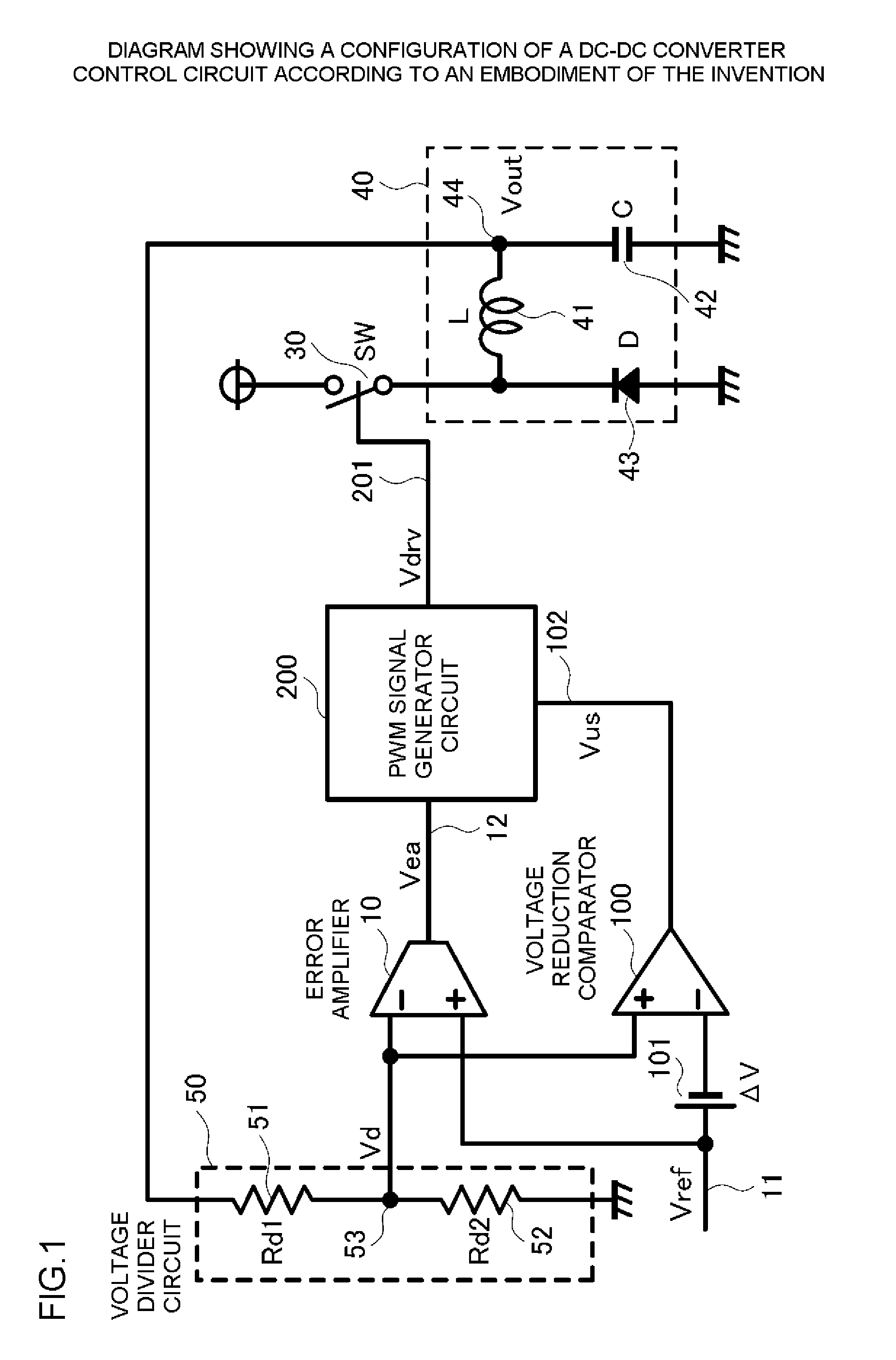
[0019]FIG. 1 is a diagram showing a configuration of a DC-DC converter control circuit according to an embodiment of the invention. The DC-DC converter control circuit according to the embodiment of the invention shown in FIG. 1 is configured in such a way that there is provided a voltage reduction comparator 100 that outputs an interrupt signal when a feedback voltage Vd of an output voltage Vout 44 of the DC-DC converter is lower than a voltage reduction threshold value (hereafter referred to as “Vref−ΔV”) set lower than a reference voltage Vref, and an interrupt signal is supplied to a PWM signal generator circuit 200 in accordance with a level value of an output Vus 102 of the voltage reduction comparator 100 obtained from the result of a comparison by the voltage reduction comparator 100 of the feedback voltage Vd 53 and the voltage “Vref−ΔV” set to be lower than the reference voltage Vref 11 by the predetermined voltage ΔV 101. As a configuration other than this is the same as...


PUM


Abstract

A control circuit of a DC-DC converter that has a switching element, including an error amplifier that amplifies a difference between a reference voltage and a feedback voltage corresponding to an output voltage of the DC-DC converter, a voltage reduction comparator that outputs an interrupt signal when the feedback voltage is lower than a voltage reduction threshold that has a value lower than that of the reference voltage, and a pulse-width modulation (PWM) signal generator circuit. The PWM signal generator circuit generates a PWM signal of a predetermined frequency based on the voltage difference when no interrupt signal is generated, or otherwise generates a switch drive signal to activate the switching element for a first period of time corresponding to the difference output by the error amplifier, and to deactivate the switching element for a second period of time after the first period of time has elapsed.

Description

BACKGROUND OF THE INVENTION[0001]1. Technical Field[0002]The present invention relates to a technology that, by interrupting a normal pulse-width modulation (PWM) control and carrying out a control whereby an ON time of a switching element is repeated before and after a predetermined OFF time, suppresses an output voltage reduction when the output voltage of a DC-DC converter drops below a predetermined value due to a load current suddenly increasing, or the like.[0003]2. Related Art[0004]FIG. 4 is a diagram showing a configuration of a general DC-DC converter control circuit for controlling an output voltage of a heretofore known DC-DC converter. In FIG. 4, an error amplifier 10 amplifies the difference between a reference voltage Vref 11 and a feedback voltage Vd 53 acquired by a voltage division of a DC-DC converter output voltage Vout 44 in a voltage divider circuit 50 that has a voltage divider resistor Rd151 and a voltage divider resistor Rd252, and outputs an output voltage V...

Claims


Application Information

Patent Timeline
Patent Type & Authority Patents(United States)
IPC IPC(8): H02M3/156
CPCH02M3/156
Inventor YAMADA, KOUHEI
Owner FUJI ELECTRIC CO LTD
Why Eureka
Try Eureka