
Dynamic aircraft headlight and method of operating a dynamic aircraft headlight

a technology of dynamic aircraft and headlights, which is applied in the field of aircraft headlights, can solve the problems of large number of headlights, a lot of mounting space on the aircraft, and a lot of wiring effort for power and control lines, and achieves good visibility, sufficient breadth, and good visibility. the effect of landing targ

Active Publication Date: 2018-03-20
GOODRICH LIGHTING SYST GMBH
View PDF5 Cites 3 Cited by
  • Summary
  • Abstract
  • Description
  • Claims
  • Application Information

AI Technical Summary

Benefits of technology

The dynamic aircraft headlight system reduces the number of lights required by combining functionalities, enhances visibility with adaptable light distributions, and eliminates blind spots, while maintaining efficient power consumption and thermal management.

Problems solved by technology

The large number of headlights requires a lot of mounting space on the aircraft and a lot of wiring efforts for power and control lines.
It is pointed out, however, that a combining of the functionality of previously separate headlights is not the only beneficial way of making use of the dynamic aircraft headlight.
The number of LEDs poses a limitation on the number of combinations of switched on LEDs.
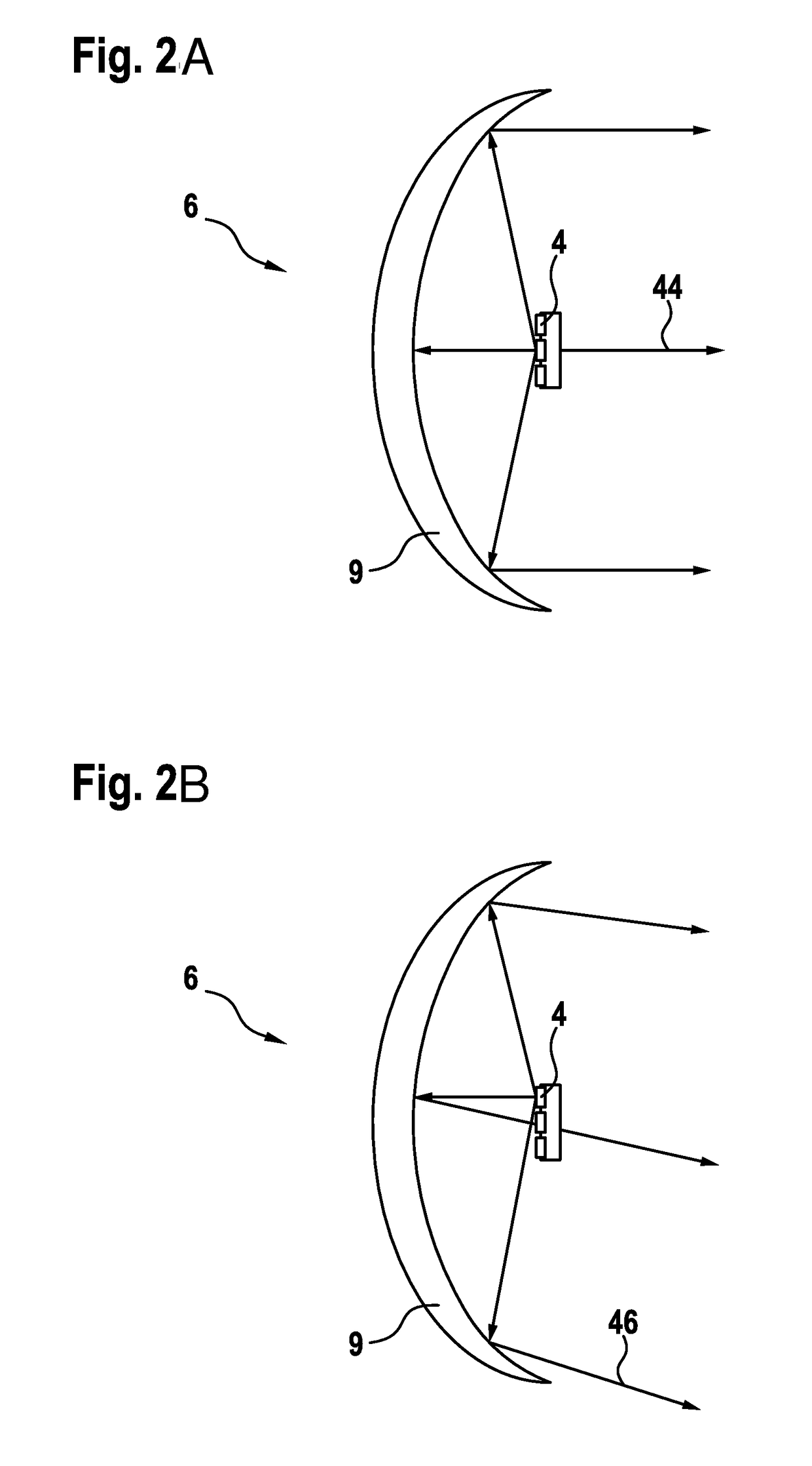
It is, however, also possible that the combination of the output light intensity distributions of all operating modes forms a non-symmetrical light intensity distribution.

Method used


Image

  • Dynamic aircraft headlight and method of operating a dynamic aircraft headlight
  • Dynamic aircraft headlight and method of operating a dynamic aircraft headlight
  • Dynamic aircraft headlight and method of operating a dynamic aircraft headlight

Examples


Embodiment Construction

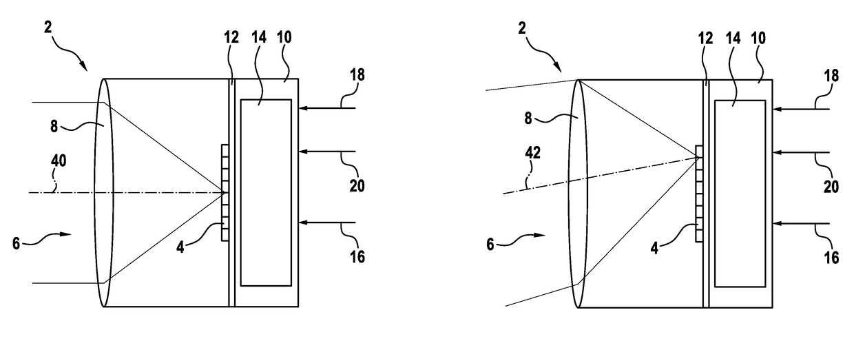
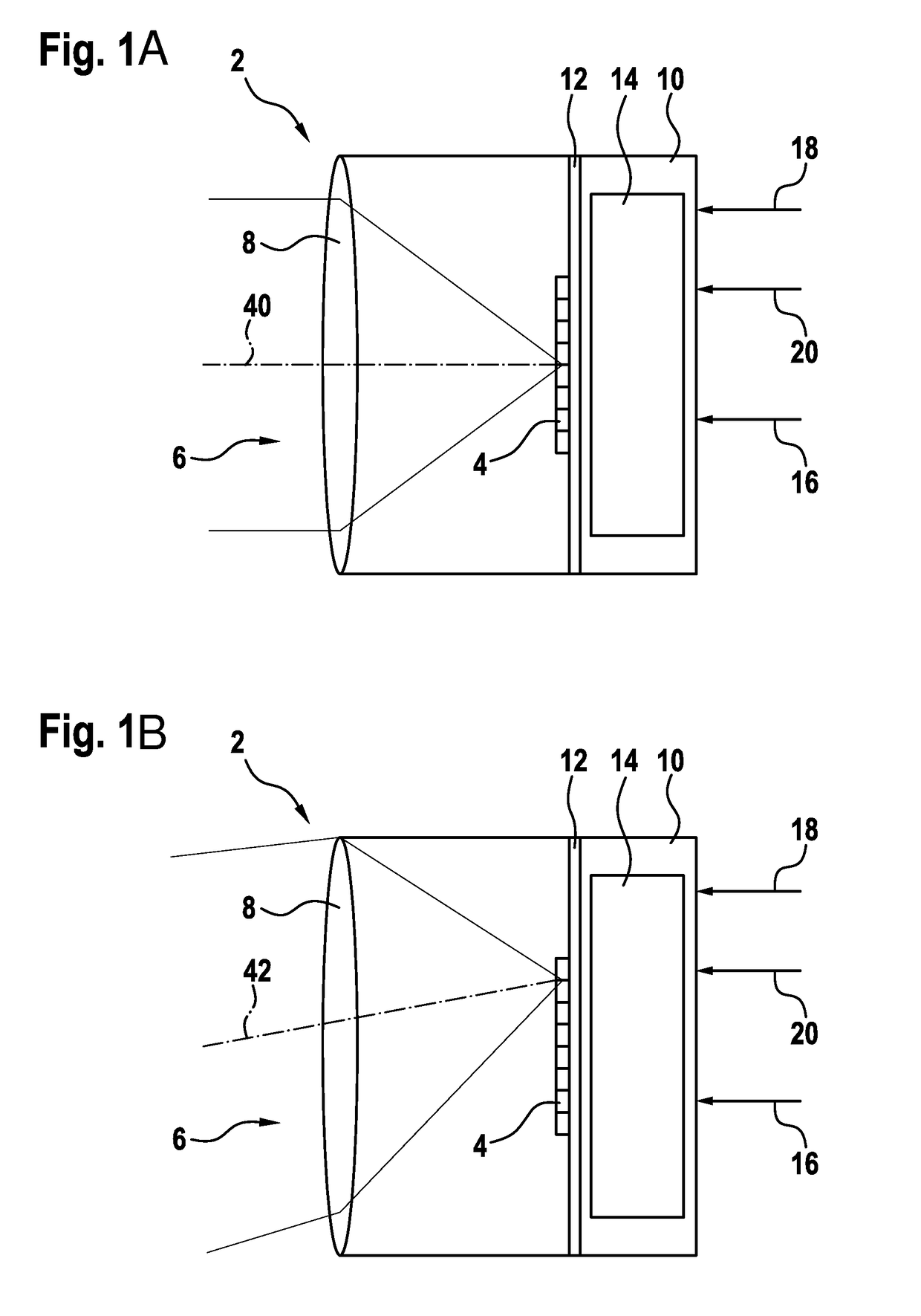
[0052]FIG. 1A shows a schematic illustration of a dynamic aircraft headlight 2 in accordance with an exemplary embodiment of the invention. The dynamic aircraft headlight 2 comprises a housing 10, whose inner space is separated into two parts by a mounting plate 12. Attached to the mounting plate 12, there is provided an LED group 4. The LED group 4 consists of eight individual LEDs arranged in a linear configuration in the exemplary embodiment of FIG. 1A. The dynamic aircraft headlight 2 further comprises an optical system 6. In the exemplary embodiment of FIG. 1A, the optical system 6 consists of a lens 8. In operation, the LEDs of the LED group 4 emit light towards the lens 8 of the optical system 6.

[0053]On the other side of the mounting plate 12, there is provided a control unit 14. The control unit 14 is coupled to a power input 16, to a flight condition data input 18 and to a ground roll sensor input 20. In this way, the control unit 14 receives power from an external power s...


PUM


Abstract

A dynamic aircraft headlight, includes an LED group, having a plurality of LEDs, and an optical system, comprising at least one optical element, for shaping an output light intensity distribution from the light emitted by the LED group. The LED group and the optical system are stationary within the dynamic aircraft light unit, with each LED of the LED group has a set position with respect to the optical system and with a light output of each LED being affected differently by the optical system.

Description

FOREIGN PRIORITY[0001]This application claims priority to European Patent Application No. 14 184 792.1 filed Sep. 15, 2014, the entire contents of which is incorporated herein by reference.TECHNICAL FIELD[0002]The present invention is in the field of exterior aircraft lighting. In particular, the present invention relates to aircraft headlights, i.e. such lights that help the pilots of the aircraft to view the environment in front of them, when operating the aircraft.BACKGROUND OF THE INVENTION[0003]Large commercial aircraft have many different exterior lights. An exemplary group of exterior aircraft lights are lights for passive visibility, such as navigation lights and anti-collision lights. Another example of exterior aircraft lights are headlights that allow the pilots to view the area in front of them, when they are seated in the cockpit. Large commercial aircraft have a variety of different headlights, such as taxi lights, take off lights, landing lights, and runway turn off l...

Claims


Application Information

Patent Timeline
Patent Type & Authority Patents(United States)
IPC IPC(8): B64D47/02B64D47/04B64D47/06F21W111/06F21Y115/10
CPCB64D47/04B64D47/02F21Y2115/10F21W2111/06B64D47/06F21W2107/30B60Q1/085B60Q1/10
Inventor HESSLING VON HEIMENDAHL, ANDRE
Owner GOODRICH LIGHTING SYST GMBH
Learn More