
Distributor device for cooling air within an engine

a distribution device and engine technology, applied in the direction of machines/engines, stators, mechanical equipment, etc., can solve the problems of limited effect of plate arrangement in providing improved cooling airflow distribution, localised hot spots and accompanying hardware deterioration, and downstream components deterioration

Inactive Publication Date: 2018-03-20
ROLLS ROYCE PLC
View PDF15 Cites 6 Cited by
  • Summary
  • Abstract
  • Description
  • Claims
  • Application Information

AI Technical Summary

Benefits of technology

This patent describes a device that can distribute air in a non-uniform manner, meaning that the air can be directed to certain areas or segments around the device with different flow rates. This is useful for situations where there are asymmetrical needs for air, such as in engine architecture. The device has a deflecting surface with a varying curvature or curve function at different angular positions, which allows for more favorable air direction and flow rate in certain directions. Overall, this device can improve the uniformity of cooling or other air effects on various components.

Problems solved by technology

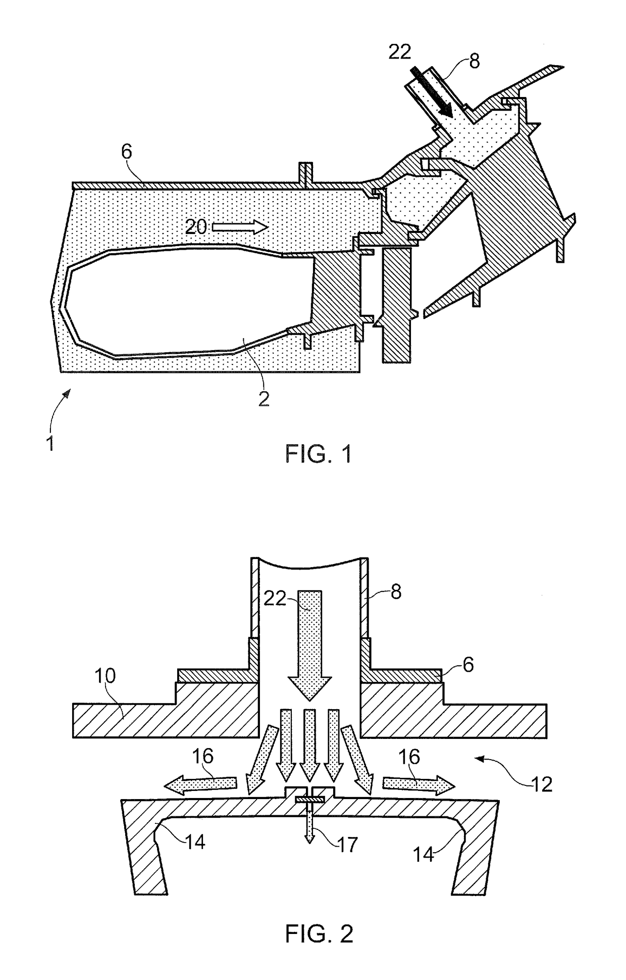
For instance:There is uneven distribution of the cooling air, leading to localised hot spots and accompanying hardware deterioration.In some arrangements where modulated HP3 air flow is introduced into the engine via independently controllable valves arranged in the HP3 air delivery system, the modulated and non-modulated air pipes may not be interspersed symmetrically, which results in over half the circumference of some of the pipes not receiving direct HP3 air input.The current system encourages leakage flow of air past strip seals which are typically located between the IP NGV's by the blowing of cooling HP3 air straight onto them.It also encourages heat pickup from the gaspath components owing to the airflow's direct impinging thereon.
This can lead to deterioration of downstream components due to the delivery thereto of higher temperature cooling air.It also encourages thermal cracking of gaspath components owing to the introduction of localised high thermal gradients.
However, these known splash plate arrangements are of only limited efficacy in providing improved cooling airflow distribution, and many, if not all, of the above-mentioned problems still remain to some degree.

Method used


Image

  • Distributor device for cooling air within an engine
  • Distributor device for cooling air within an engine
  • Distributor device for cooling air within an engine

Examples


first embodiment

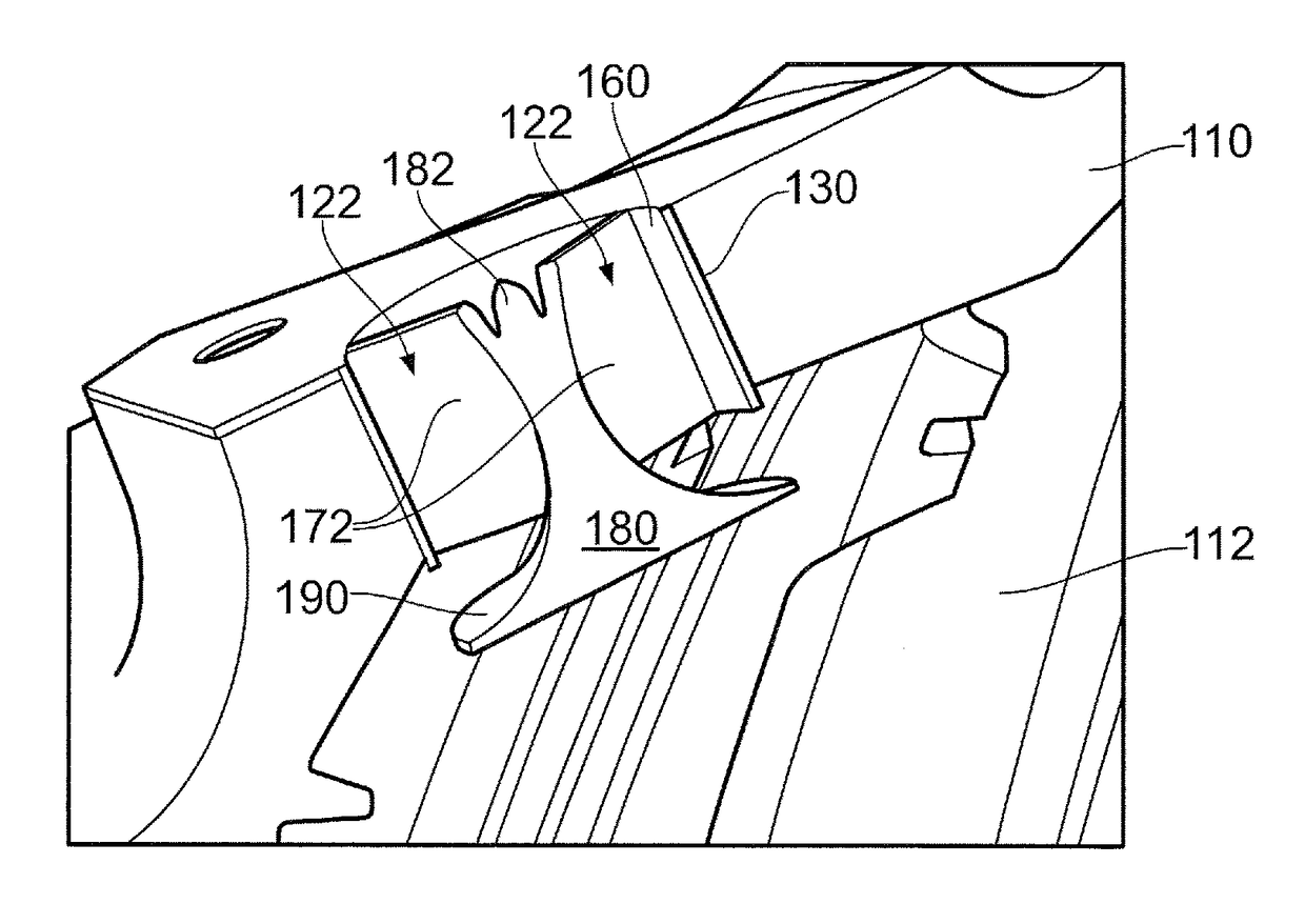
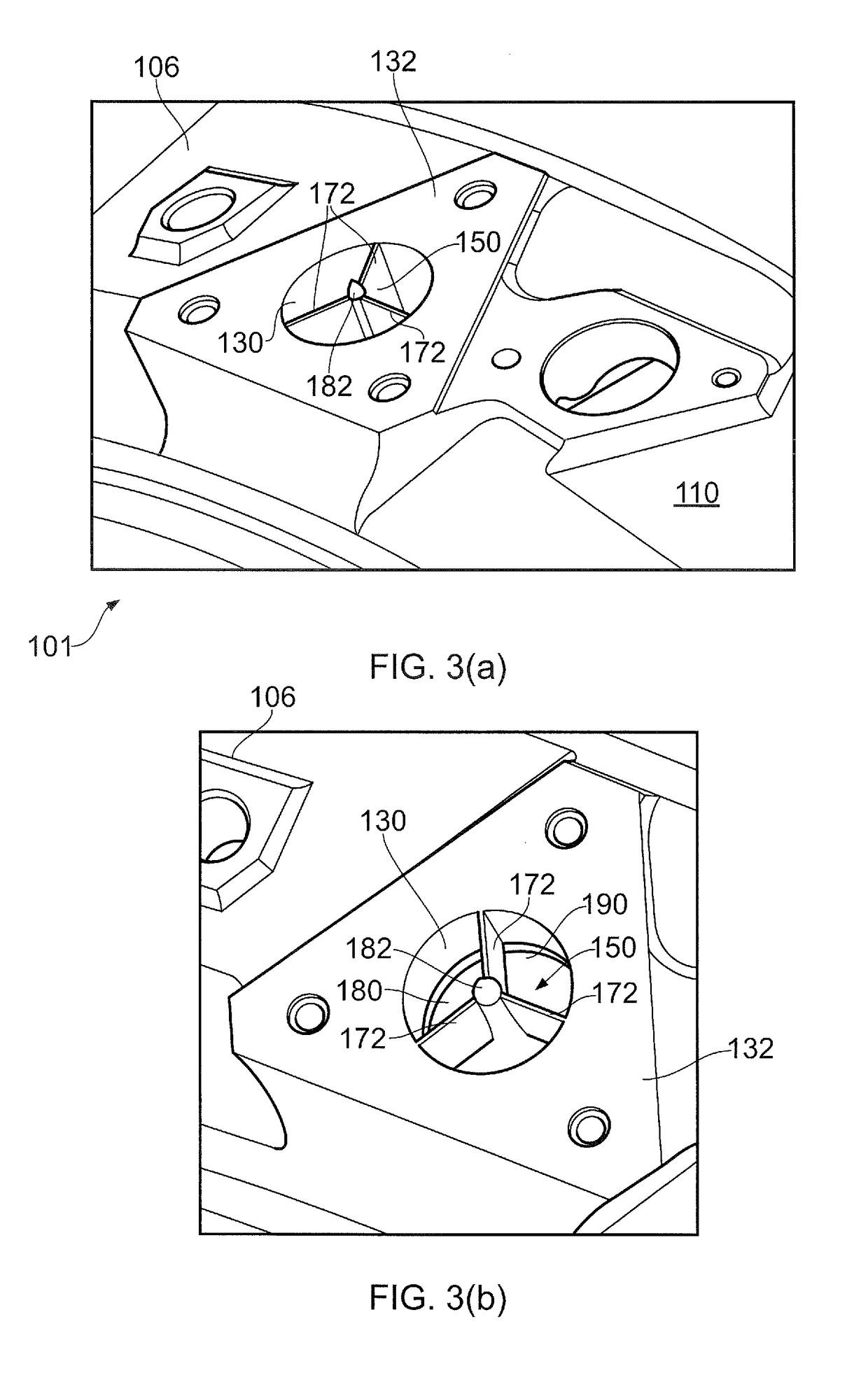
[0111]The air deflector 180 which characterises this first embodiment of distributor device according to the invention comprises a deflecting surface 190 in the shape of the exterior of a bell of a trumpet. Thus, the deflecting surface 190 is rotationally substantially symmetrical about the longitudinal axis of air inlet 130 (and thus also the central axial spine 182 of the deflector 180). In other words, the deflecting surface 190 has a substantially uniform curved profile when viewed in all cross-sectional planes parallel to the said longitudinal axis of air inlet 130 (and thus the central axial spine 182 of the deflector 180). That curvature may for example be defined by a mathematical function representing a circular or elliptical arc, a parabola, a hyperbola, any combination of any of the aforementioned curve functions, or of any other suitable smoothly curved shape. The deflecting surface 190 may if desired be advantageously smoothed or polished in order to lower the frictiona...

second embodiment

[0127]In this second embodiment of distributor device 350, the deflector 380 is constructed and configured so as to bias the cooling airflow in one of two opposite directions with a higher (or lower) flow rate than in the other one of the two opposite directions, in order for example to account for asymmetrical air feed pipe distributions within the engine architecture.

[0128]In this second embodiment the general manner of mounting of the distributor device 350 on the engine manifold 310 within air inlet 330 substantially corresponds to that of the first embodiment of FIGS. 3 and 5, as will be readily appreciated and understood by persons skilled in the art. However, in this second embodiment the configuration and arrangement of the deflecting surface 390 of the deflector 380 is different.

[0129]As illustrated in FIGS. 6(a) to (e), in this second embodiment the deflecting surface 390 is split into discrete first 390A and second 390B oppositely facing deflecting surface portions, for t...


PUM


Abstract

A distributor device for distributing cooling air within a gas turbine engine, the device including a base mountable adjacent an inlet for air to be distributed; and a deflector supported by the base and in fluid communication with the air inlet, the deflector being configured to direct air from the air inlet in a plurality of directions within the engine; wherein the deflector includes one or more deflecting surfaces curvilinearly configured to direct the air differentially in a plurality of desired directions within the engine. In embodiments the deflecting surface(s) is / are curved and are so configured such that air from the air inlet is directable either: (i) in directions of travel in each of a plurality of desired different, non-parallel directions within the engine; or (ii) in each of a plurality of desired different directions within the engine with different flow rates.

Description

TECHNICAL FIELD[0001]This invention relates to a distributor device for engine cooling air. More particularly the invention relates to a distributor device for distributing and / or directing cooling air within an engine, especially a gas turbine engine.BACKGROUND[0002]The advent of modern turbofan engines saw the introduction of a fundamental change in 3-shaft engine architecture, namely a change to a single skin high pressure (HP) turbine. The 3-shaft engine architecture requires three separate compressor offtakes to feed different temperature cooling air to each of the three turbines. In prior engines concentrically mounted cases have been used to achieve the separation and transfer of the three compressor cooling air flows.[0003]One consequence of the change to a single skin casing has been the need to transport HP3 cooling air from the HP compressor to the HP turbine via large bore pipes routed around the outside of the engine core. The HP3 air delivery pipework into the intermed...

Claims


Application Information

Patent Timeline
Patent Type & Authority Patents(United States)
IPC IPC(8): F01D9/06F01D11/24F02C7/18
CPCF01D9/065F01D9/06F02C7/18F01D11/24Y02T50/675Y02T50/60
Inventor MANZOORI, REZABALSDON, JULIAN GLYN
Owner ROLLS ROYCE PLC
Learn More