Distributor device for cooling air within an engine
a distribution device and engine technology, applied in the direction of machines/engines, stators, liquid fuel engines, etc., can solve the problems of limited effect of plate arrangement in providing improved cooling airflow distribution, localised hot spots and accompanying hardware deterioration,
- Summary
- Abstract
- Description
- Claims
- Application Information
AI Technical Summary
Benefits of technology
Problems solved by technology
Method used
Image
Examples
first embodiment
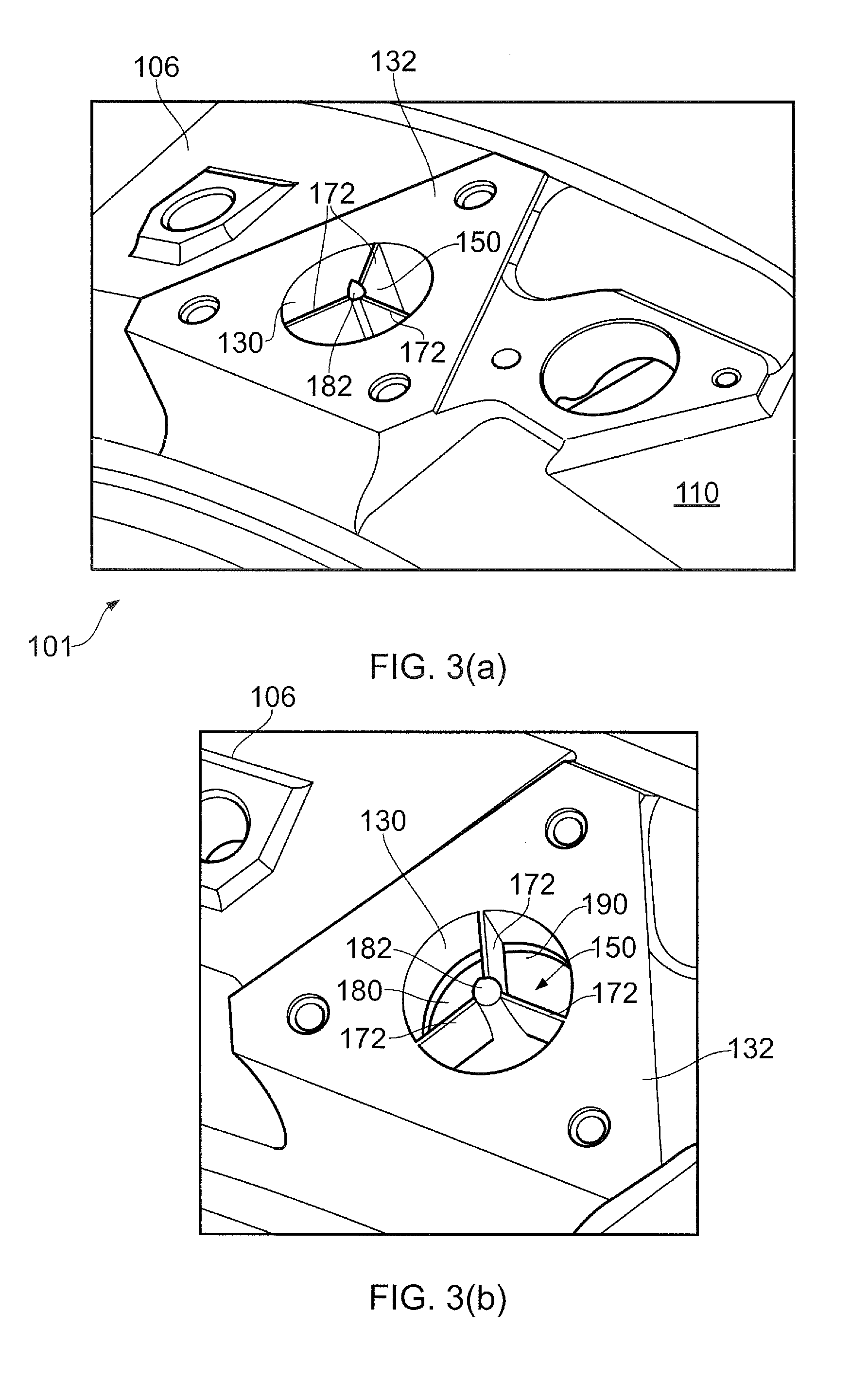
[0108]The air deflector 180 which characterises this first embodiment of distributor device according to the invention comprises a deflecting surface 190 in the shape of the exterior of a bell of a trumpet. Thus, the deflecting surface 190 is rotationally substantially symmetrical about the longitudinal axis of air inlet 130 (and thus also the central axial spine 182 of the deflector 180). In other words, the deflecting surface 190 has a substantially uniform curved profile when viewed in all cross-sectional planes parallel to the said longitudinal axis of air inlet 130 (and thus the central axial spine 182 of the deflector 180). That curvature may for example be defined by a mathematical function representing a circular or elliptical arc, a parabola, a hyperbola, any combination of any of the aforementioned curve functions, or of any other suitable smoothly curved shape. The deflecting surface 190 may if desired be advantageously smoothed or polished in order to lower the frictiona...
second embodiment
[0124]In this second embodiment of distributor device 350, the deflector 380 is constructed and configured so as to bias the cooling airflow in one of two opposite directions with a higher (or lower) flow rate than in the other one of the two opposite directions, in order for example to account for asymmetrical air feed pipe distributions within the engine architecture.
[0125]In this second embodiment the general manner of mounting of the distributor device 350 on the engine manifold 310 within air inlet 330 substantially corresponds to that of the first embodiment of FIGS. 3 and 5, as will be readily appreciated and understood by persons skilled in the art. However, in this second embodiment the configuration and arrangement of the deflecting surface 390 of the deflector 380 is different.
[0126]As illustrated in FIGS. 6(a) to (e), in this second embodiment the deflecting surface 390 is split into discrete first 390A and second 390B oppositely facing deflecting surface portions, for t...
PUM
 Abstract
Description
Claims
Application Information
 - R&D
- Intellectual Property
- Life Sciences
- Materials
- Tech Scout
- Unparalleled Data Quality
- Higher Quality Content
- 60% Fewer Hallucinations
Browse by: Latest US Patents, China's latest patents, Technical Efficacy Thesaurus, Application Domain, Technology Topic, Popular Technical Reports.
© 2025 PatSnap. All rights reserved.Legal|Privacy policy|Modern Slavery Act Transparency Statement|Sitemap|About US| Contact US: help@patsnap.com


