Diaphragm device for video camera lens and method for controlling diaphragm device

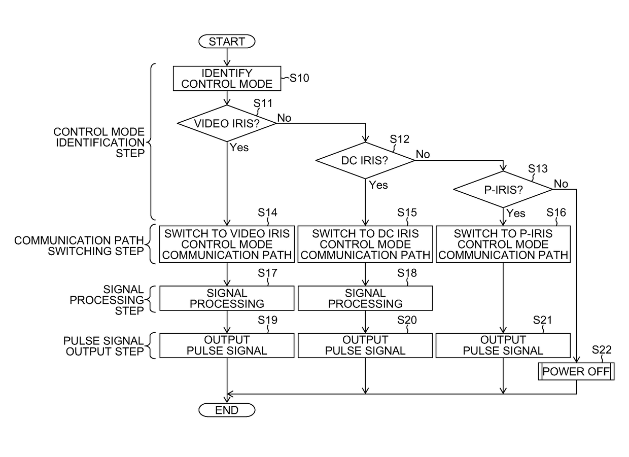
a technology of diaphragm and video camera, which is applied in the direction of dynamo-electric converter control, exposure control, instruments, etc., can solve the problems of connected camera body being unable to appropriately perform diaphragm control of lens, and conventional arts like ptl 1-3 cannot appropriately perform diaphragm control in p-, so as to achieve accurate identification of control mode and signal voltage detection

Active Publication Date: 2018-03-20
FUJIFILM CORP
View PDF15 Cites 1 Cited by
  • Summary
  • Abstract
  • Description
  • Claims
  • Application Information

AI Technical Summary

Benefits of technology

[0033]The aspect enables accurate detection of signal voltage because the step of detecting the signal communicated via the plurality of terminals (input / output unit) is performed after total closing of the diaphragm for the video camera lens, and thereby enables accurate identification of the control mode.
[0035]The aspect allows drive of the pulse signal driven motor to be appropriately controlled even if the communication signal is a signal different from the pulse signal because a pulse signal is obtained and output by signal processing from the transmitted and received communication signal even if the communication signal different from the pulse signal is transmitted and received (communicated) via the plurality of terminals (input / output unit).
[0038]The aspect enables acquisition of a pulse signal by the signal processing units and output of the pulse signal to the actuator even if the communication signal is identified as a control mode incapable of driving the actuator.
[0052]The aspect enables accurate detection of signal voltage because the step of detecting a signal communicated via the plurality of terminals (input / output unit) is performed after total closing of the diaphragm for the video camera lens, and thereby enables accurate identification of the control mode. Especially, this aspect works on detection of whether or not a control mode is the DC iris control mode.

Problems solved by technology

Because these video iris control mode, DC iris control mode, and P-iris control mode have totally different control configurations, it is not possible, for example, to use a lens unit equipped with a diaphragm device in the P-iris control mode for a camera body compatible with the video iris control mode.
This causes a situation of the connected camera body being unable to perform diaphragm control of the lens in the P-iris control mode.
Therefore, conventional arts like PTL 1-3 cannot appropriately perform diaphragm control in the P-iris control mode using the stepping motor.

Method used


Image

  • Diaphragm device for video camera lens and method for controlling diaphragm device
  • Diaphragm device for video camera lens and method for controlling diaphragm device
  • Diaphragm device for video camera lens and method for controlling diaphragm device

Examples


Embodiment Construction

[0059]Embodiments of the present invention will be explained below referring to the attached drawings.

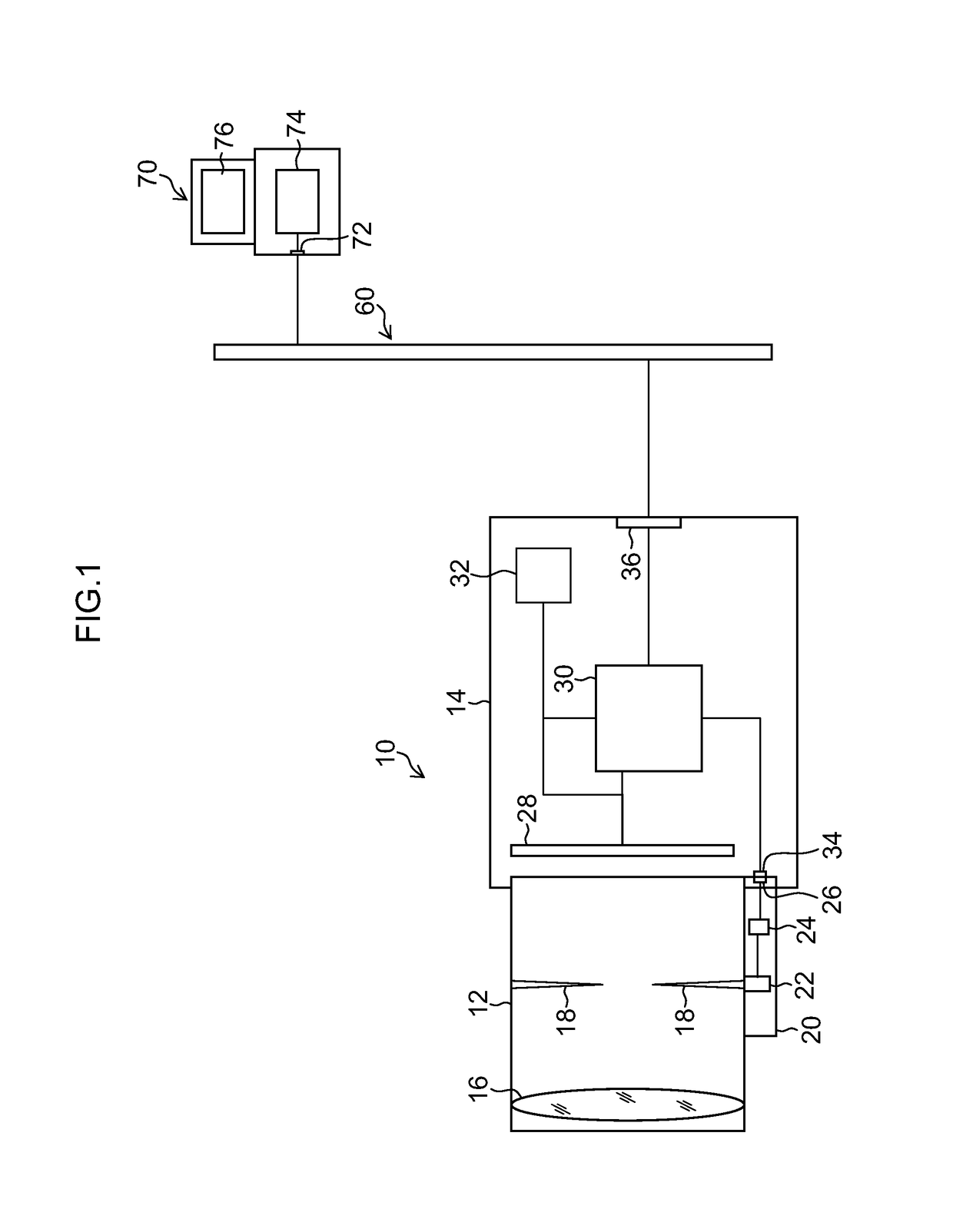
[0060]FIG. 1 is a block diagram designating an overview of a video camera connected with a management station via a network.

[0061]A video camera 10 capable of taking still images and moving images comprises an interchangeable lens unit 12 (diaphragm device for a video camera lens), and a video camera body 14 including an imaging element 28. The lens unit 12 and the video camera body 14 are electrically connected via a lens unit connector 26 of the lens unit 12 and a camera body connector 34 of the video camera body 14. The lens unit 12 can be interchangeably attached to the video camera body 14 outputting a pulse signal for diaphragm control and the video camera body 14 outputting a signal for diaphragm control different from the pulse signal.

[0062]The lens unit 12 comprises an optical system including a lens 16, an iris (diaphragm) 18, a filter (not designated) and the like, and an...


PUM


Abstract

A diaphragm device includes a diaphragm mechanism, a connector, an identification unit for identifying a control mode of a signal communicated via the multiple terminals on the basis of voltage of the signal, and a control unit, wherein the switching unit switches the communication path so that a pulse signal capable of driving the pulse signal driven actuator is generated for generating the pulse signal on the basis of the signal, and output to the pulse signal driven actuator if the control mode of the signal is identified as one based on a control mode incapable of directly driving the pulse signal driven actuator; and the switching unit switches the communication path so that the signal is output to the pulse signal driven actuator if the control mode of the signal is identified as a first control mode based on a pulse signal directly driving the pulse signal driven actuator.

Description

CROSS-REFERENCE TO RELATED APPLICATIONS[0001]This application is a Continuation of PCT International Application No. PCT / JP2013 / 078524 filed on Oct. 22, 2013, which claims priority under 35 U.S.C § 119(a) to Japanese Patent Application No. 2013-073946 filed on Mar. 29, 2013. Each of the above application(s) is hereby expressly incorporated by reference, in its entirety, into the present application.BACKGROUND OF THE INVENTION[0002]Field of the Invention[0003]The present invention relates to a diaphragm device for a video camera lens and a method for controlling the diaphragm device, and in particular, to a video camera lens capable of adjusting the amount of diaphragm by an actuator using a pulse signal driven motor.[0004]Description of the Related Art[0005]Imaging devices such as video cameras generally adopt a scheme in which a lens unit comprising a diaphragm mechanism is attached to a camera body.[0006]Regarding such a diaphragm mechanism of the lens unit, a DC iris control mode...

Claims


Application Information

Patent Timeline
Patent Type & Authority Patents(United States)
IPC IPC(8): G03B9/07G02B5/00H04N5/238G03B7/20H02P8/00G05D3/10H04N5/232
CPCG03B9/07G02B5/005G03B7/20H02P8/00H04N5/238G05D3/10H04N5/23241H04N23/65H04N23/75
Inventor KUWAKINO, KOSHIHAMANA, AKINORINAGATA, KOUICHIYAMAMOTO, SHINICHINAKAMURA, HIROSHI
Owner FUJIFILM CORP
Why Eureka
Try Eureka