Lighting system for a stadium

a stadium and lighting technology, applied in the field of lighting systems and methods, can solve the problems of difficult alignment of luminaires, difficult to accurately determine the aiming spot, and difficulty in achieving the expected or desired homogeneous lighting effect, and achieve the effect of enhancing the effect of adjacent light differences or errors

Active Publication Date: 2018-03-20
SIGNIFY HLDG BV
View PDF12 Cites 0 Cited by
  • Summary
  • Abstract
  • Description
  • Claims
  • Application Information

AI Technical Summary

Benefits of technology

[0007]According to an embodiment of the invention, there is provided a light system for a stadium, the light system comprising: at least one sensor configured to determine light intensity values for multiple locations within the stadium; multiple electronically controllable luminaires, wherein at least one electronically controllable luminaire is configured to generate light directed towards at least one location of the multiple locations within the stadium based on a received control parameter; a controller configured to receive the light intensity values from the at least one sensor, further configured to determine a light intensity difference based on the light intensity values from the multiple locations within the stadium, and configured to select the at least one electronically controllable luminaire and generate the control parameter for the least one electronically controllable luminaire based on the light intensity difference to attempt to reduce the light intensity difference.
[0037]Generating at least one control parameter for at least one electronically controllable luminaire based on the light intensity difference may comprise generating the control parameter to minimise a combination of a light intensity difference based on the light intensity values from the multiple locations as sensed from a first direction and a light intensity difference based on the light intensity values from the multiple locations as sensed from a second direction. The combination of the light intensity difference based on the light intensity values from the multiple locations as sensed from a first direction and a light intensity difference based on the light intensity values from the multiple locations as sensed from a second direction may comprise a combination with a first weighting factor associated with the light intensity difference based on the light intensity values from the multiple locations as sensed from a first direction and a second weighting factor associated with the light intensity difference based on the light intensity values from the multiple locations as sensed from a second direction.

Problems solved by technology

From the luminaire location, the installer has a clear overview of the field but it is very difficult to accurately determine the aiming spot.
The alignment of the luminaires is prone to errors and the beam patterns generated by the luminaires may be difficult to align and combine to provide the expected or desired homogeneous lighting effect.
However such a method does not enable the fine tuning of an implemented lighting plan to provide a homogeneous lighting effect.
Furthermore such a system would be difficult to control once implemented.

Method used


Image

  • Lighting system for a stadium
  • Lighting system for a stadium
  • Lighting system for a stadium

Examples


Embodiment Construction

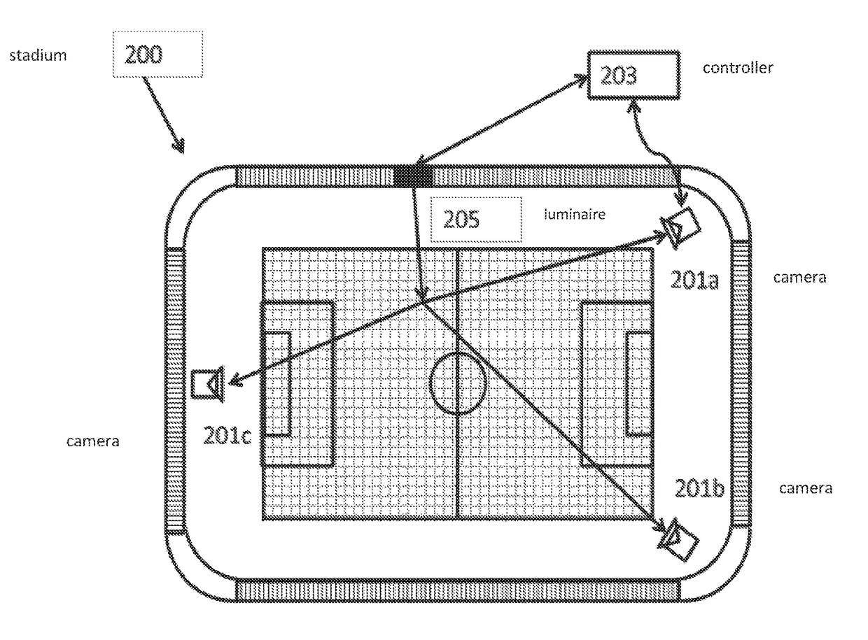
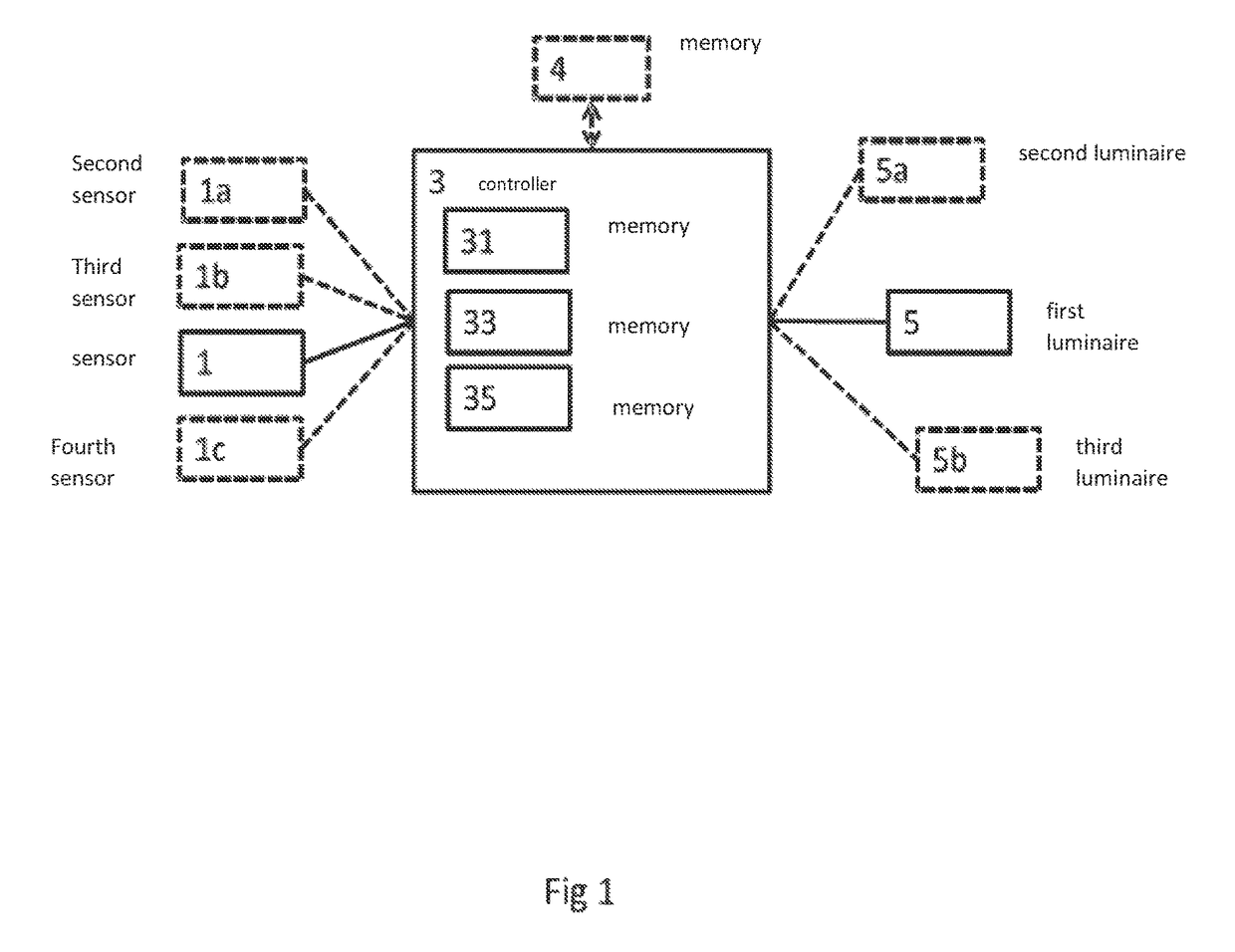
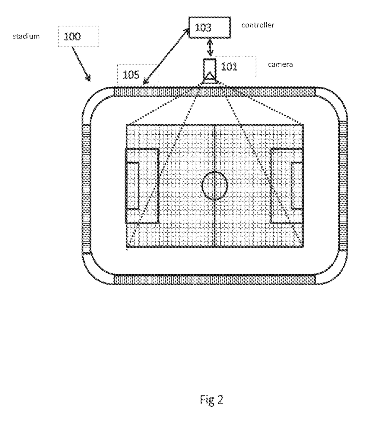
[0057]The concepts as described with respect propose the implementation of lighting intensity homogeneity measurement and control apparatus in combination with individually electronically controllable (for example individually dimmable) pitch or field lighting luminaires. Although the following example have been described with respect to stadium or arenas such as football stadia, it would be understood that the apparatus and methods described herein could be applied to various large scale lighting applications such as lighting for swimming pool arenas and velodromes. Thus the term “arena” or “stadium” within the document and the claims herein should be interpreted broadly to cover any architectural or façade lighting system. Such architectural or façade lighting system may illuminate a surface, which surface may be the ground, water, a structure, or any other surface that may receive illumination from the lighting system. The surface may be flat, curved, tilted, rough, smooth, or ha...


PUM


Abstract

A light system for a stadium, the light system comprising: at least one sensor configured to determine light intensity values for multiple locations within the stadium; at least one electronically controllable luminaire configured to generate light directed towards at least one location of the multiple locations within the stadium based on a received control parameter; a controller configured to receive the light intensity values from the at least one sensor, further configured to determine a light intensity difference based on the light intensity values from the multiple locations within the stadium, and configured to select the at least one electronically controllable luminaire and generate the control parameter for the least one electronically controllable luminaire based on the light intensity difference to attempt to reduce the light intensity difference.

Description

CROSS-REFERENCE TO PRIOR APPLICATIONS[0001]This application is the U.S. National Phase application under 35 U.S.C. §371 of International Application No. PCT / EP2015 / 067417A1, filed on Jul. 29, 2015 which claims the benefit of European Patent Application No. 14180993.9, filed on Aug. 14, 2014. These applications are hereby incorporated by reference herein.FIELD OF THE INVENTION[0002]This invention is generally related to a light or lighting system and method, and in particular a lighting system with lighting intensity homogeneity control which is compatible with arena or stadium lighting systems.BACKGROUND OF THE INVENTION[0003]In high-end arena (field, pitch or stadium) lighting, like the Philips ArenaVision products, a large number of luminaires are distributed around an arena or stadium to attempt to create a uniform light intensity on the field or pitch. For example a football stadium may have a lighting plan or design where the lighting system contains more than 100 luminaires ea...

Claims


Application Information

Patent Timeline
Patent Type & Authority Patents(United States)
IPC IPC(8): H05B37/02H05B44/00
CPCH05B37/02H05B37/0227H05B39/041H05B45/10H05B47/105Y02B20/00
Inventor KNIBBE, ENGEL JOHANNESSTADLER, FLORIANVAN HOOF, WILLEM PIETSIMPSON, MICHAEL DAVID
Owner SIGNIFY HLDG BV
Why Eureka
Try Eureka