Rapid 3D cardiac parameter mapping

a 3d and fast technology, applied in the field of medical fluoroscopy, can solve the problems of insufficient speed of point-by-point mapping and time-consuming mapping procedures,

Active Publication Date: 2019-04-16
APN HEALTH
View PDF22 Cites 0 Cited by
  • Summary
  • Abstract
  • Description
  • Claims
  • Application Information

AI Technical Summary

Benefits of technology

[0008]It is an object of this invention to provide a method for rapidly determining the 3D locations of a plurality of radio-opaque sensors placed in a living heart by using single-plane fluoroscopic images from two different angles.
[0010]Another object of this invention is to provide a method which accurately generates and displays such 3D maps when the two angular fluoroscopic views are captured sequentially.
[0012]A further object of this invention is to provide a method for rapid 3D mapping which operates in conjunction with a fluoroscopic system configured to automatically determine the 3D location and orientation of a radio-opaque medical object in a living system using only single-plane fluoroscopy.
[0015]Yet another object of this invention is to provide a method for rapid generation and display of cardiac parameter maps with more than one such map displayed at the same time.
[0037]The term “cardio-respiratory phase” as used herein refers to the phase of combined cardiac and respiratory motions. Therefore, as used herein, minimizing the difference between the cardio-respiratory phases of two images may also include minimizing a combination of measures of both cardiac phase and respiratory phase.

Problems solved by technology

Such mapping procedures can be time-consuming, and often the imaging modality utilized to capture geometric data for the mapping process requires patient exposure to X-rays.
Maps generated on a point-by-point basis cannot be generated fast enough to be useful in such circumstances.

Method used


Image

  • Rapid 3D cardiac parameter mapping
  • Rapid 3D cardiac parameter mapping
  • Rapid 3D cardiac parameter mapping

Examples


embodiment 300

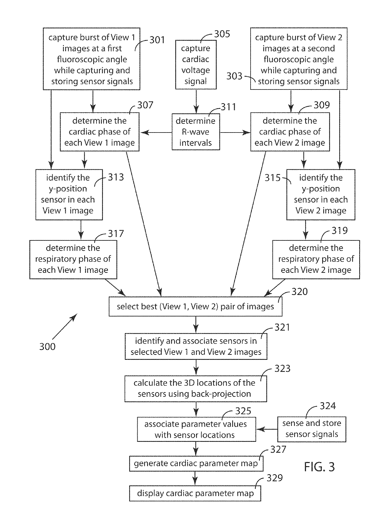
[0068]FIG. 3 is a schematic block diagram illustrating an embodiment 300 of the inventive method for rapidly generating a 3D map of a cardiac parameter in a region of a living heart into which region a plurality of catheters, each having one or more radio-opaque sensors, has been placed. The method uses single-plane fluoroscopic images taken from two different angles (View 1 and View 2) in order to enable calculation of the 3D locations of the sensors. In the exemplary method presented herein, the sensors are cardiac electrodes measuring voltages, and the parameter map is a local activation time (LAT) map. The inventive method involves the use of one or more programmable computers to carry out the image processing, signal processing and other computational steps involved. In addition to the plurality of sensors, apparatus to sense cardiac rhythm, such as an R-wave detector with its associated electrodes, may be required to supply a signal from which the cardiac phase of the single-p...

embodiment 380

[0102]The primary mesh is then subdivided (adding more points and smaller intervening surfaces) in order to produce a more accurate surface which has all mesh points close to such surface. Method steps 391 through 395 and loop path 397 together comprise an iterative mesh-smoothing process which enables the final primary mesh to appear more natural (more like a physiological structure). In method step 391, additional intermediate mesh points are added to the primary mesh by a process of subdivision, and the resulting mesh is smoothed in method step 393. Laplacian and cotangent smoothing are among the smoothing approaches which may be applied in smoothing step 393. In decision step 395, the mesh is tested against smoothing criteria to determine if the mesh has nearly uniform edges of length below a predetermined threshold. If the criteria are not satisfied, the mesh is iteratively modified by looping back along loop path 397 to subdivision method step 391 and proceeds further until th...

embodiment 403

[0110]In embodiment 403, method step 324 is again shown separately to indicate explicitly that sensing and storing of cardiac parameter data to be associated with the 3D location data may be generated during initialization as well as during normal operation of C3DLS 20. The computational load, data sensing, and timing requirements of both RCPMS 400 and C3DLS 20 are such that the method steps of both systems are carried out within programmable computing equipment. It is anticipated that in many instances both RCPMS 400 and C3DLS 20 may be operating within the same computing equipment and both make use of one or more computer displays driven by such computing equipment. This is illustrated in FIG. 15 by output 407 of RCPMS 400 merging with output 409 of C3DLS 20 to generate and display one or more physiological maps. As above, observation and subsequent inputs by the user are illustrated by a dotted-line feedback pathway 403.

[0111]FIG. 16 is an exemplary LAT map similar to that of FIG...


PUM


Abstract

A method for generating a 3D map of a cardiac parameter in a region of a living heart, the method using single-plane fluoroscopic images and comprising: (a) placing a plurality of catheters each having one or more radio-opaque sensors into the region such that the locations of the sensors geometrically span the region; (b) capturing a first-view digitized 2D image of the region from a first fluoroscope positioned at a first angle; (c) identifying each of the plurality of sensors in the first-view image; (d) capturing a second-view digitized 2D image of the region from a second fluoroscope positioned at a second angle which is different from the first angle; (e) identifying each of the plurality of sensors in the second-view image; (f) associating each of the plurality of identified sensors in the second-view image with its corresponding identified sensor in the first-view image; (g) sensing and storing values of the cardiac parameter with each of the plurality of sensors; (h) determining the 3D location of each of the plurality of sensors from the first-view and second-view images using back-projection calculations; (i) associating each of the parameter values with its corresponding sensor location; (j) generating the parameter map from the first-view and second-view images; and (k) displaying the parameter map on a display device.

Description

FIELD OF THE INVENTION[0001]This invention is related generally to the field of medical fluoroscopy, and more particularly to technology for rapid measurement and display of cardiac parameter values within a living heart.BACKGROUND OF THE INVENTION[0002]Mapping of physiological structures and various physiological parameters sensed within the body is an important technological component of the practice of medicine. Such mapping procedures can be time-consuming, and often the imaging modality utilized to capture geometric data for the mapping process requires patient exposure to X-rays. The time during which a patient undergoes a mapping procedure and the accompanying interventional treatment and the patient's total exposure to X-ray radiation are both important risk factors for medical mapping procedures; both time and X-ray exposure are desirably minimized.[0003]The inventive method disclosed herein is directed toward generating such maps much more rapidly, and although the inventi...

Claims


Application Information

Patent Timeline
Patent Type & Authority Patents(United States)
IPC IPC(8): A61B6/00A61B5/0432A61M25/01A61B5/044A61B5/0408A61B90/00
CPCA61B6/503A61B5/044A61B5/0432A61B5/04085A61B6/4266A61B6/463A61B6/481A61B6/487A61B6/5205A61B6/5217A61M25/0108A61B6/466A61B2090/3966A61B6/12A61B6/4417A61B6/4441A61B6/5235A61B6/527A61B6/5288G16H50/30A61B5/6852A61B6/547A61B6/584A61B18/1492A61B5/113A61B5/721A61B2017/00053A61B5/287A61B5/339A61B5/352A61B5/0071A61B5/282A61B5/333
Inventor SRA, JASBIRKOHUT, SHIVANIBRODNICK, DONALD
Owner APN HEALTH
Why Eureka
Try Eureka