
Bearing with minimized leakage of lubricant

a technology of bearings and lubricants, applied in the direction of bearings, machines/engines, mechanical equipment, etc., can solve the problems of bearing damage, bearing additional service costs, and low level of lubricant within the bearings,

Active Publication Date: 2018-04-10
SIEMENS GAMESA RENEWABLE ENERGY AS
View PDF20 Cites 0 Cited by
  • Summary
  • Abstract
  • Description
  • Claims
  • Application Information

AI Technical Summary

Benefits of technology

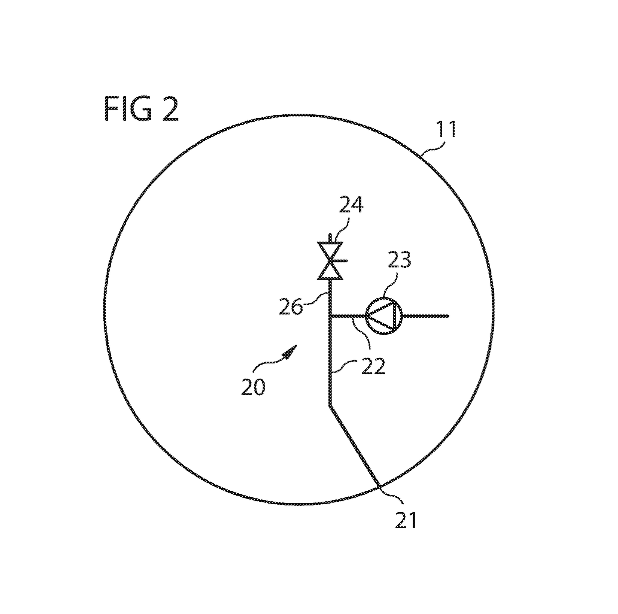
This patent involves a bearing that is lubricated with a lubricant to reduce wear and fatigue. The bearing is also sealed to minimize the amount of lubricant that leaks out. The bearing has a ventilation device with at least one pressure compensation hole that allows pressure to equalize between the sealed bearing and the ambient. A compressor unit is added to ensure that the pressure compensation hole remains unobstructed and that overpressure inside the bearing is minimized. This results in reduced leakage of lubricant and improved bearing safety. The ventilation device also reduces wear on the seals which further improves bearing safety and reduces service costs.

Problems solved by technology

If uncontrolled leakage occurs, the level of lubricant within the bearing could become low.
If a bearing is operated at low level of lubricant, detrimental damages may be the consequence for the bearing due to wear and fatigue.
In addition, an elevated rate of leakage of lubricant may lead to additional service costs due to increased service activities of cleaning and filling up the lubricant containers at the wind turbine.
In particular, leakage of lubricant on offshore wind turbines may lead to significantly elevated service costs.
In practice, it may occur, though, that elevated amounts of lubricant may leak out of the bearing.
It has been shown that even a relatively small overpressure inside the bearing, e.g. 0.1 bar, may over time lead to significant leakage.
Elevated overpressure inside the bearing, e.g. 0.2 bar or higher, may even lead to a significant leakage of lubricant in relatively short time.
One drawback of this solution is, however, that the pressure compensation hole may be blocked or obstructed by grease.
It is not desired to continuously blow air from the outside into the inside of the bearing, as this might even lead to a situation of undesired overpressure inside the bearing.
From a structural point of view, construction and provision of such a large bearing may pose significant challenges.
As a considerable amount of lubricant exists inside the bearing, the potential risk of a considerable amount of lubricant leaking out of the bearing exists.
Thus, gravity forces may not be enough to ensure an efficient and reliable discharge of the used lubricant.
Note that in conventional bearings of a wind turbine with no efficient ventilation system, the existing overpressure inside the bearing facilitates pressing the used lubricant out of the bearing.
As the overpressure inside the bearing is reduced or even avoided at all with the inventive system, the escape of used lubricant via the one or more lubricant drain holes is in general more difficult.

Method used


Image

  • Bearing with minimized leakage of lubricant
  • Bearing with minimized leakage of lubricant
  • Bearing with minimized leakage of lubricant

Examples


Embodiment Construction

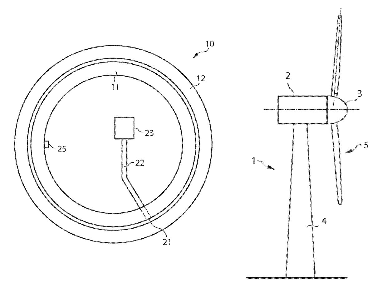
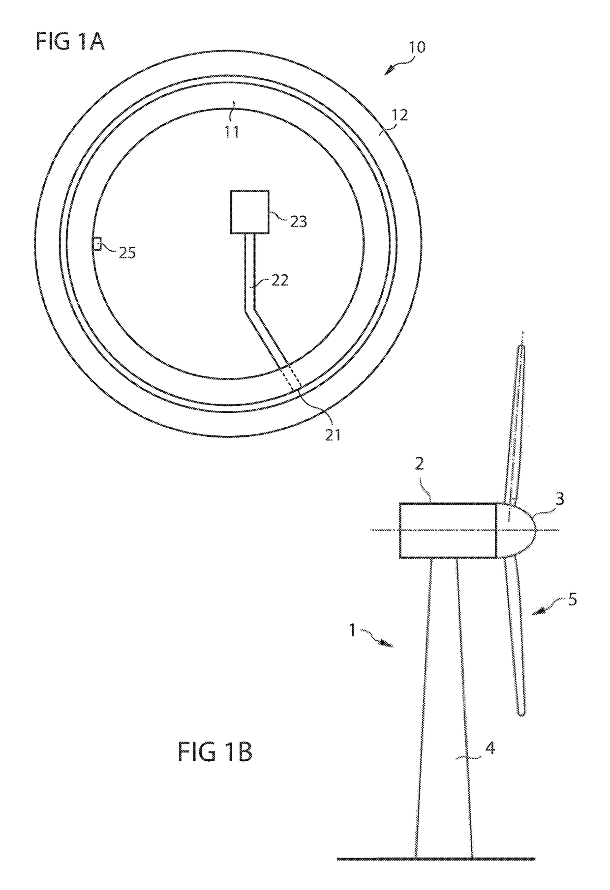
[0057]FIG. 1A shows a bearing 10 of a wind turbine 1 (not depicted), wherein the bearing 10 comprises an inner bearing ring 11 and an outer bearing ring 12. FIG. 1B depicts the wind turbine 1 according to an embodiment. In the example as illustrated in FIG. 1A, the inner bearing ring 11 is stationary and the outer bearing ring 12 is rotatable. Referring now to both FIGS. 1A and 1B, this has to be understood that the inner bearing ring 11 is stationary relative to the nacelle 2 and the tower 4 of the wind turbine 1, while the outer bearing ring 12 is rotatable relative to the nacelle 2 of the wind turbine 1. Relative to the hub 3 and the rotor blades 5 of the wind turbine 1, the outer bearing ring 12 is stationary and the inner bearing ring 11 is rotatable. The inner bearing ring 11 and the outer bearing ring 12 both have an annular shape and are arranged in a co-axial manner in the example of FIG. 1A. The bearing may for example be a roller bearing such as a three-roller bearing or ...


PUM


Abstract

A bearing of a wind turbine, wherein the bearing is lubricated with a lubricant for reducing wear and fatigue of the bearing, the bearing is sealed such that the amount of lubricant which is leaking out of the bearing is minimized, is provided. The bearing includes a ventilation device with at least one pressure compensation hole for enabling a pressure compensation between the sealed bearing and the ambient. The ventilation device further includes a compressor unit, which is connected with the pressure compensation hole. Thus, a compressed medium can be selectively blown through the pressure compensation hole to ensure that the pressure compensation hole remains substantially unobstructed such that overpressure within the bearing compared to the ambient is minimized and leakage of lubricant out of the bearing is reduced. A wind turbine including such bearing and an associated method is also provided.

Description

CROSS-REFERENCE TO RELATED APPLICATIONS[0001]This application claims priority to European Application No. EP 15164441.6, having a filing date of Apr. 21, 2015, the entire contents of which are hereby incorporated by reference.FIELD OF TECHNOLOGY[0002]The following relates to a bearing of a wind turbine, wherein the bearing comprises a ventilation device. Furthermore, the invention relates to a wind turbine with such a bearing and to a method of reducing leakage of lubricant out of such a bearing.BACKGROUND[0003]The leakage of lubricant out of a bearing is advantageously kept as low as possible in order to ensure that a desired amount of lubricant remains within the bearing. If uncontrolled leakage occurs, the level of lubricant within the bearing could become low. If a bearing is operated at low level of lubricant, detrimental damages may be the consequence for the bearing due to wear and fatigue.[0004]In addition, an elevated rate of leakage of lubricant may lead to additional serv...

Claims


Application Information

Patent Timeline
Patent Type & Authority Patents(United States)
IPC IPC(8): F16C33/66F16C37/00F03D80/70F16C19/52F16C33/72
CPCF16C33/6607F03D80/70F16C19/52F16C33/726F16C37/007Y02E10/722F05B2260/64F16C2300/14F16C2360/31F16C33/1025Y02E10/72
Inventor MOELLER, TROELS KILDEMOESTHOMSEN, THYGE SKOVBJERG
Owner SIEMENS GAMESA RENEWABLE ENERGY AS
Learn More