Waveguide device with switchable polarization configurations

a technology of switchable polarization and waveguide, which is applied in the direction of polarised antenna unit combination, instruments, optical elements, etc., can solve the problem of difficulty in mechanical movemen

Active Publication Date: 2018-04-10
KVH IND INC
View PDF14 Cites 3 Cited by
  • Summary
  • Abstract
  • Description
  • Claims
  • Application Information

AI Technical Summary

Benefits of technology

The described embodiments have the advantage of controlling the linear polarization skew by rotating circular waveguide subassemblies. This eliminates the need for extra flexible cables and heavy load bearings to rotate the larger mass behind the reflector vertex. The configuration remains fixed to the back of the antenna reflector, resulting in a more efficient and compact design.

Problems solved by technology

The technical problem addressed in this patent text is the need for a terrestrially-based transceiver station to be able to receive and transmit microwave energy with different polarizations, particularly for satellite communication systems. The polarization of the antenna is important for maximizing power transfer between radio links, and the polarization angle of the transceiver station must match the polarization angle of the satellite for maximum power transfer. Prior art solutions involve rotating the entire transceiver, which can be heavy and difficult to mechanically move, and may require flexible cables/waveguide assemblies to accommodate the rotation. The patent text proposes a solution to this problem.

Method used


Image

  • Waveguide device with switchable polarization configurations
  • Waveguide device with switchable polarization configurations
  • Waveguide device with switchable polarization configurations

Examples


Embodiment Construction

[0041]A description of example embodiments of the invention follows.

[0042]The teachings of all patents, published applications and references cited herein are incorporated by reference in their entirety.

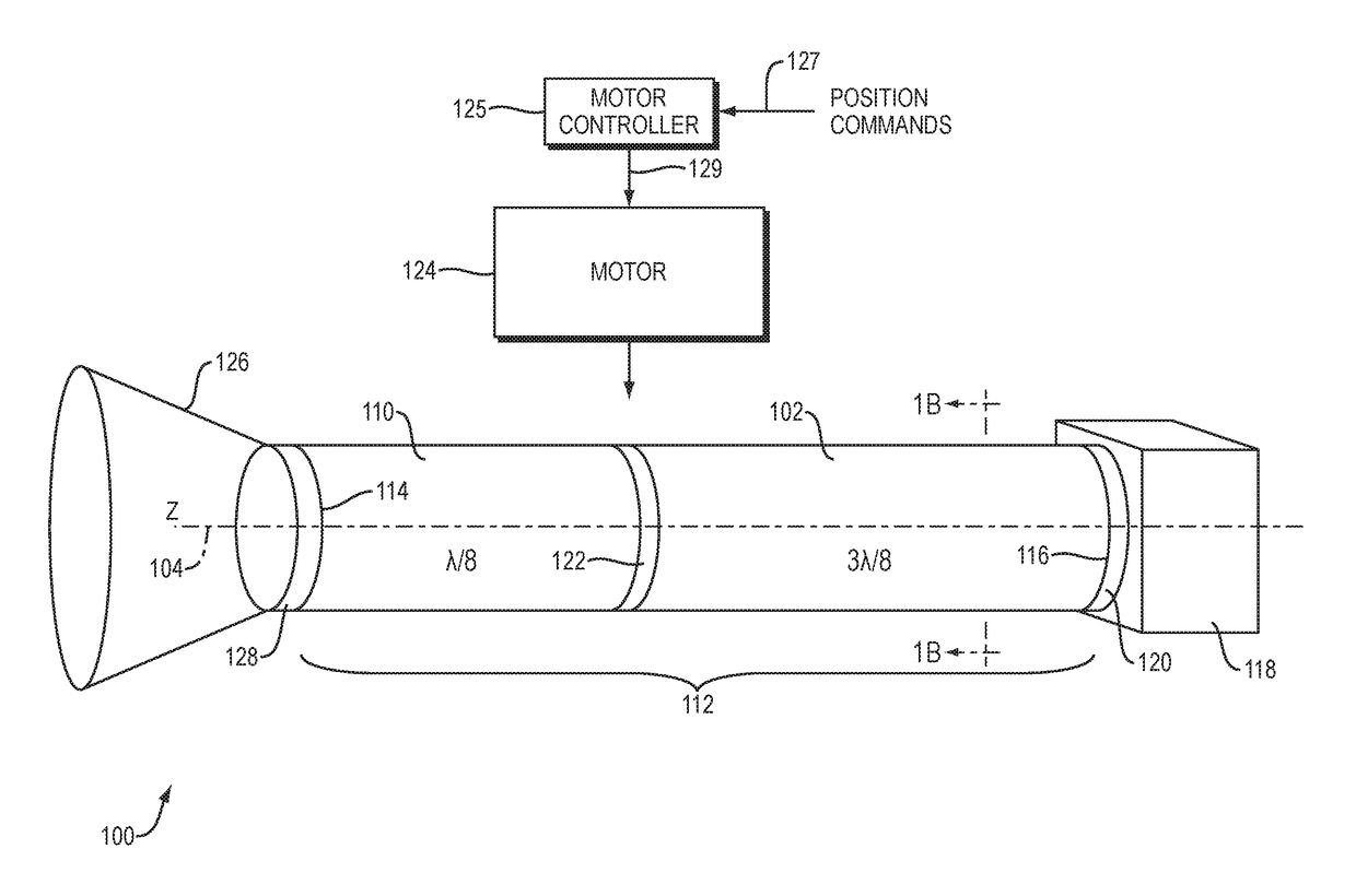
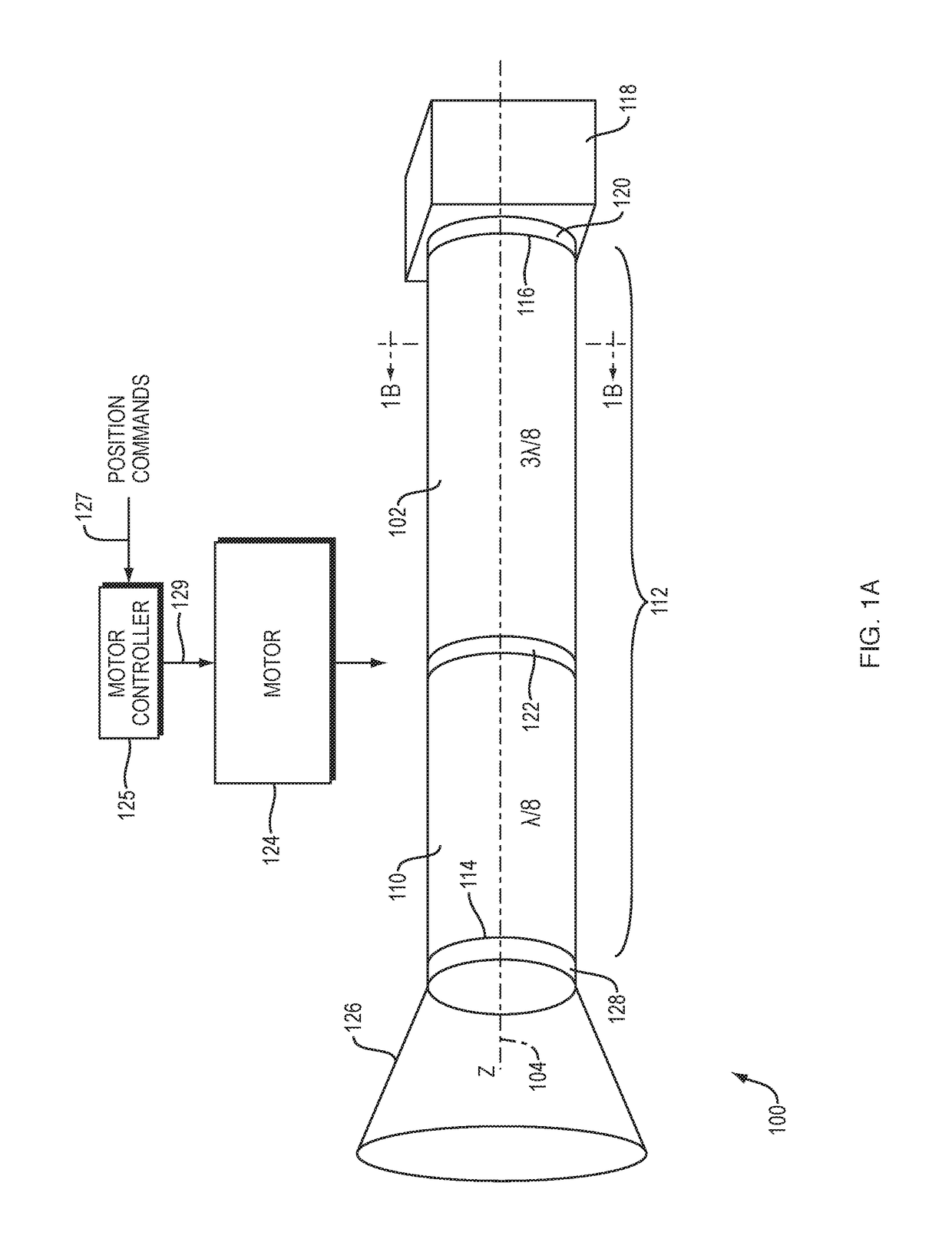
[0043]FIG. 1A illustrates an example embodiment of a circular waveguide polarization device 100 constructed and arranged according to the described embodiments. The example device 100 comprises a first circular waveguide 102 configured to implement a 3λ / 8 relative phase shift between two orthogonal linear polarized signals transmitted into the first circular waveguide 102 at a first polarization orientation.

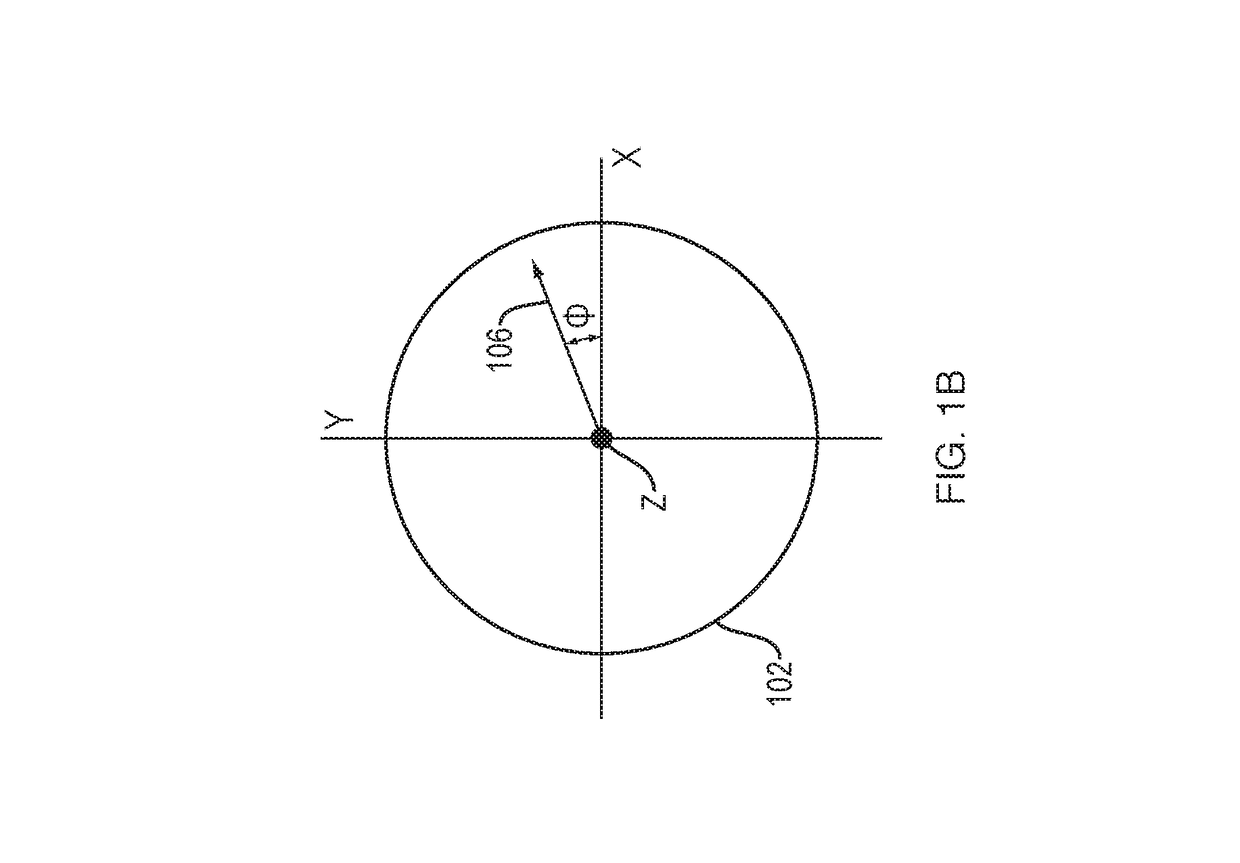
[0044]As used herein, the “polarization orientation” of a signal refers the angular orientation of the transmitted signal's electrical field vector, with respect to a reference coordinate system. FIG. 1B an example of such a coordinate system. FIG. 1B shows a sectional view of a circular waveguide (e.g., first circular waveguide 102), with the Z axis being the longitudinal axis 10...


PUM


Abstract

A waveguide device comprises a first circular waveguide segment (CWS) that imparts a 3λ/8 relative phase shift to two orthogonal linearly polarized signals, and a second CWS that imparts a λ/8 relative phase shift to two orthogonal linearly polarized signals. A waveguide assembly (WGA) comprises the first CWS disposed coaxially adjacent to the second CWS. A source may provide dual linear polarized energy into the WGA. In a first mode, the first CWS is axially orientated relative to the second CWS, such that the first CWS polarization is offset by 90° degrees with respect to the second CWS polarization. The radiation source polarization may be offset by 45° relative to the first CWS polarization and the second CWS polarization. In a second mode, the first CWS may be orientated with respect to the second CWS, such that the first CWS polarization and the second CWS polarization are substantially the same.

Description


Claims


Application Information

Patent Timeline
Owner KVH IND INC
Why Eureka
Try Eureka