Multi-channel laser device with fiber array

a laser device and fiber array technology, applied in the field of optical communication technology, can solve the problems of increasing equipment cost, difficult production of optical devices, and precise manufacturing equipment, and achieve the effects of enhancing the linearity of the light-current-voltage curve, relatively wide area of light coupling, and relatively high coupling efficiency

Active Publication Date: 2018-04-10
GLOBAL TECH INC
View PDF21 Cites 0 Cited by
  • Summary
  • Abstract
  • Description
  • Claims
  • Application Information

AI Technical Summary

Benefits of technology

[0008]The present invention using the foregoing structure has the following advantages: the thermal expanded fiber used in the structure has a wider input mode field diameter that is usually 2.5˜3.5 times the input mode field diameter of a single-mode fiber, so this fiber may have relatively-high coupling efficiency and a relatively-wide area for light coupling; the use of an optical isolator may prevent the light, reflected by the components, from entering into the fibers, so as to enhance the linearity of the light-current-voltage (LIV) curves of fibers. Moreover, the present invention reaches the high coupling efficiency of the laser device and meanwhile requires a relatively-low precision of the equipment, so the laser components and fibers can respectively be arrayed to produce a laser device having a fiber array; and in general, 4, 8, 10 or 16 channels and so on are used, so the manufacturing cost may significantly be reduced.
[0009]As an improvement, each of the laser components includes a laser driving chip, a laser chip and a detector. The detector and the laser chip are disposed in front of the front end of the laser driving chip, and the back end of the laser chip faces the laser driving chip. A reflector is disposed between the back end of the laser chip and the detector and is configured to reflect light radiated from the back end of the laser chip to a receiving surface of the detector. In such a structure, a small amount of light radiated by the back end of the laser chip is reflected by the reflector toward the receiving surface of the detector, so the detector is capable of monitoring the operation of the laser chip. Moreover, the detector and the laser chip are disposed in front of the front end of the laser driving chip rather than beside the laser driving chip, so the components may occupy a smaller space on the module board, especially occupy the short wide of the module board, and the space occupied by the components may be minimized after the components are arrayed.
[0010]The convex lens is a cylindrical convex lens, having an end surface that is flat, and another end surface that is a salient spherical surface. Such a convex lens provides a better performance, and is easily disposed and arranged in the housing.

Problems solved by technology

Such a design leads to a great difficulty in the production of optical devices and also requires high precise manufacturing equipment whereby the cost of the equipment increases.
However, the price of a laser chip is directly proportional to its output light power so that the cost increases significantly.
Additionally, the narrow coupling area of a general fiber is merely + / −3 um, so this kind of fibers cannot be used to implement the coupling of an array of laser components.

Method used


Image

  • Multi-channel laser device with fiber array
  • Multi-channel laser device with fiber array
  • Multi-channel laser device with fiber array

Examples


Embodiment Construction

[0015]In the following detailed description, for purposes of explanation, numerous specific details are set forth in order to provide a thorough understanding of the disclosed embodiments. It will be apparent, however, that one or more embodiments may be practiced without these specific details. In other instances, well-known structures and devices are schematically shown in order to simplify the drawings.

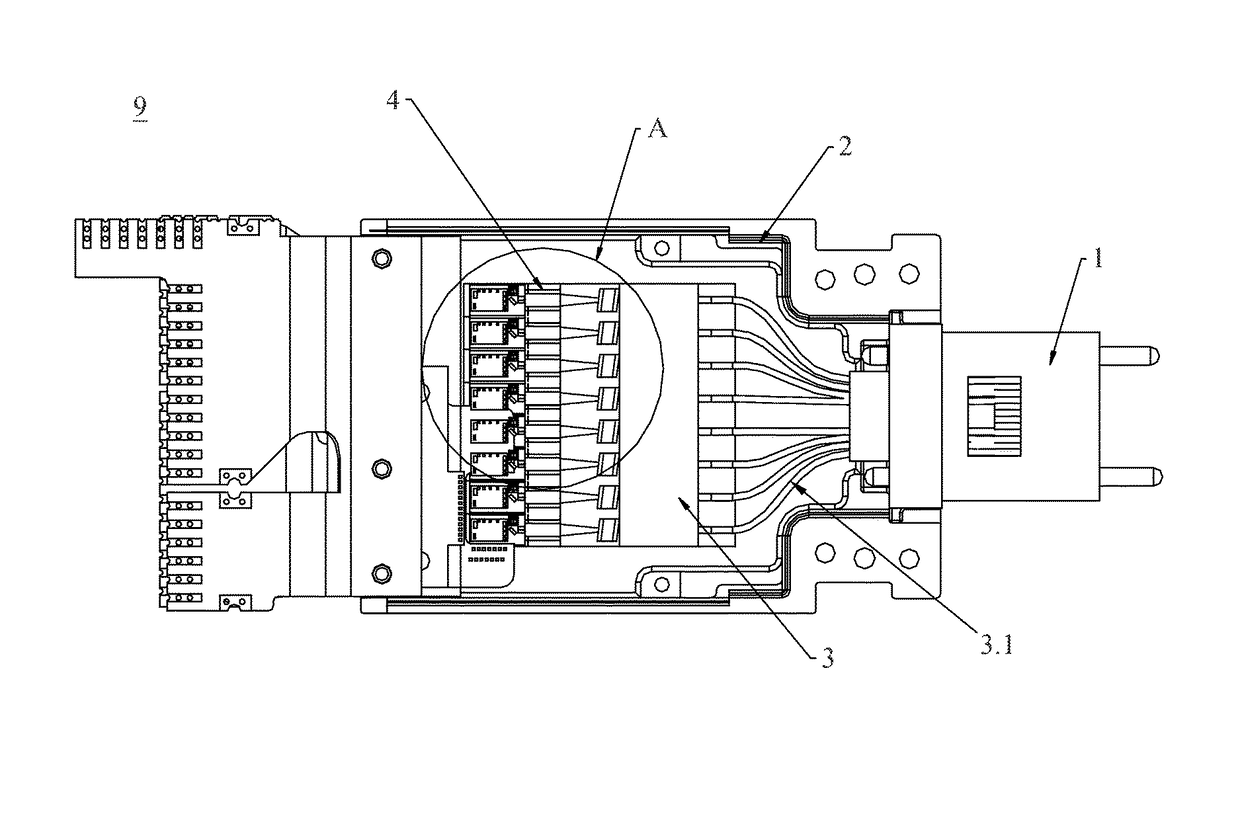
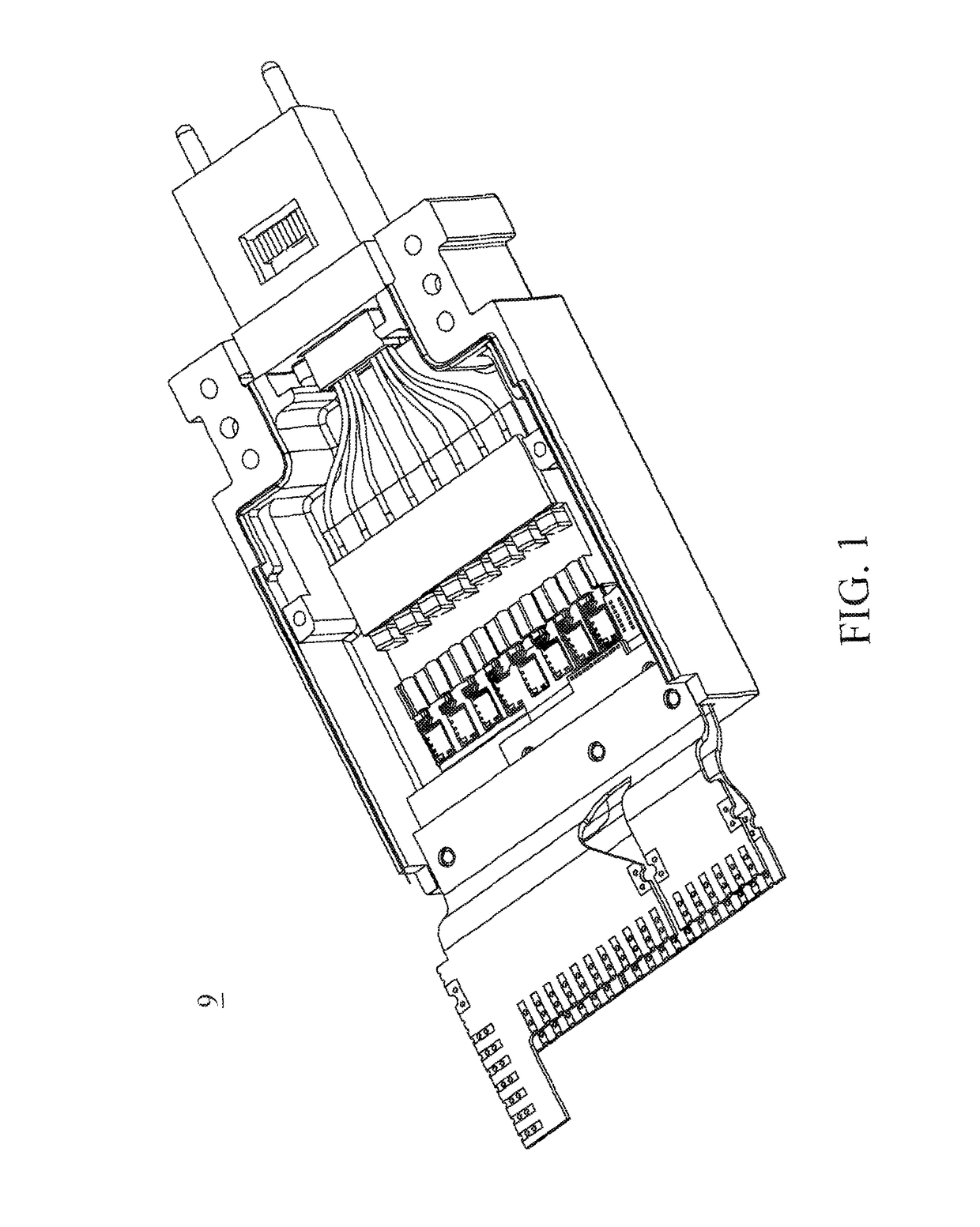
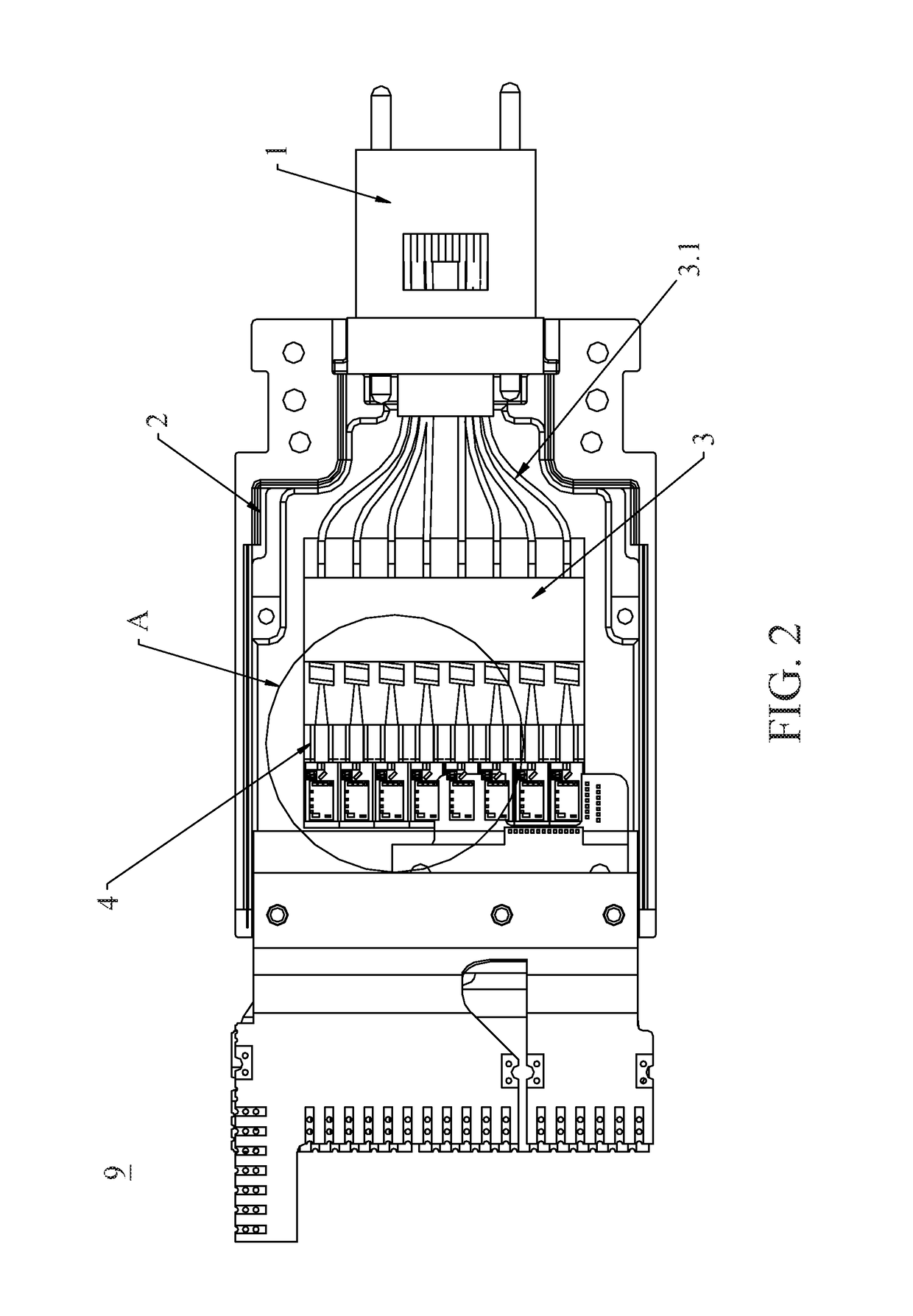
[0016]As shown in FIGS. 1, 2 and 3, the present invention provides a multi-channel arrayed laser device 9, which includes a housing 2 and a ferrule 1. In the housing 2, a plurality of laser components 4 are arranged side by side, each of the laser components 4 is connected to a fiber array module 3 through an optical isolator 4.6. The fiber array module 3 includes a plurality of thermal expanded fibers 3.1, and the fibers out of the fiber array module 3 are collected in the ferrule 1. The laser components 4 are disposed on the same module board. Laser light radiated from the front ...


PUM


Abstract

A multi-channel laser device with a fiber array includes a housing and a ferrule. In the housing, laser components are arranged side by side, and each of the laser components is connected to a fiber array module through an optical isolator. The fiber array module includes thermal expanded fibers, and fibers out of the fiber array module are collected by the ferrule. The laser components are disposed on the same module board, and laser light radiated from the front end of a laser chip in each of the laser components is projected onto the optical isolator through a convex lens and then enters into the thermal expanded fiber. Such a structure may reach a relatively-high coupling efficiency and implement the coupling of arrayed laser components.

Description

CROSS-REFERENCE TO RELATED APPLICATIONS[0001]This non-provisional application claims priority under 35 U.S.C. § 119(a) on Patent Application No(s). 201520640868.8 filed in China on Aug. 24, 2015, the entire contents of which are hereby incorporated by reference.BACKGROUND[0002]Technical Field[0003]The disclosure relates to the optical communication technology, more particularly to a multi-channel laser device with a fiber array.[0004]Related Art[0005]The existing technology of fiber laser devices usually grinds a general single-mode optical fiber until this fiber has a certain angle, e.g. about 8 degrees, at its cross-section, so that the fiber can couple to a laser component. Such a design reaches a coupling efficiency of 40˜50%, and the fiber has a relatively narrow coupling area at its maximum point. Therefore, this fiber is more sensitive to its coupling position, and while this position slightly shifts by about 1 um, the light power may reduce by more than 3 dB. Such a design l...

Claims


Application Information

Patent Timeline
Patent Type & Authority Patents(United States)
IPC IPC(8): G02B6/32G02B6/42H01S5/40H01S5/42G02B6/38
CPCG02B6/425G02B6/32G02B6/4208H01S5/4031H01S5/426G02B6/4292G02B6/3885G02B6/4206G02B6/4214G02B6/4286
Inventor LUO, JIAN-HONGTSAI, CHAO-HUNGNIE, PENGLIU, HUA
Owner GLOBAL TECH INC
Why Eureka
Try Eureka