Device and method for distributing and grouping containers

a technology for distributing containers and containers, applied in packaging, packaging, packaging bottles, etc., can solve problems such as risk of tilting, and unfavorable distribution and grouping of containers, and achieve the effect of avoiding slipping, avoiding slipping, and avoiding slipping

Active Publication Date: 2018-04-24
KRONES AG
View PDF29 Cites 7 Cited by
  • Summary
  • Abstract
  • Description
  • Claims
  • Application Information

AI Technical Summary

Benefits of technology

[0014]Selective guidance to the desired conveying lane can be effected in particular by way of a control and / or regulating unit of the transfer conveyor which, for example, activates said release mechanism and / or controls the speed of the guide elements. The control and / or regulating unit can further be adapted to also control transportation of the containers in the infeed flow and / or the outfeed flow. Smooth cooperation between the infeed, the outfeed and the transfer conveyors can thereby be ensured.
[0027]In addition to the above-described section of the transport track formed as a magnetic path along the transfer path between the reception point and the delivery point, the transport track can outside the transfer path further comprises at least one section of the path, for example, the return path, along which the conveying devices are moved at a uniform speed. The section of the path can for this purpose comprise a drive device in the form of a conveyor belt, a conveyor chain, or the like. By combining a transport path with a magnetic drive and a return path with a mechanical drive, installation costs for the entire transfer conveyor can be lowered.
[0036]According to one embodiment, the outfeed conveyor can further comprise a pair of long-stator linear motor drives arranged parallel to each other with a plurality of conveying devices connected to each other in pairs by a cross member, in particular an impact bar. The linear motor drives thus arranged are there in terms of process technology disposed downstream of the region of the outfeed conveyor in which the containers are distributed to the conveying lanes, so that non-grouped containers can be consolidated to groups by selectively moving the pairs of conveying devices. For this, the containers not yet aligned in a line perpendicular to the conveying direction can be aligned by way of the cross member. For example, the containers being transported faster than the cross member by the one or more conveyor belts of the outfeed conveyor can run against these cross members and thereby be braked. On the other hand, trailing containers can by a cross member faster running be pushed until they are in line with the leading containers. For this, the pair-forming conveying devices of the linear motor drives can by way of a control and / or regulating unit be moved accordingly, also independently of each other. The transport tracks of the linear motor drives can for returning the conveying devices comprise return paths in a plane vertically offset relative to the transport plane of the containers. The cross members, in particular in the form of impact bars, can be configured such that tilting of the containers during grouping can be prevented. In addition, the cross members can be hingedly supported at the respective conveying devices, so that the conveying devices of the pairs can be temporarily moved at different speeds in order to cause an inclined position of the cross members with respect to the perpendicular direction of the conveying direction. If required, the cross members can be formed having variable lengths, for example, by way of a spring mechanism.
[0041]According to one further development, the containers can be distributed by way of a long-stator linear motor drive with a plurality of individually and independently movable conveying devices and / or a belt or chain drive. The same developments and variations that have been previously described in connection with the linear motor drive can presently also be used. The conveying devices can in particular be moved in such an individual manner by way of a control and / or regulating unit of the transfer conveyor that their guide elements receive individual containers or groups of containers from the infeed flow and guide them specifically to the desired conveying lanes. Any gaps in the infeed flow can there be closed in that the conveying devices wait for the next container at the delivery point as needed. By accelerating the trailing conveying devices and / or decelerating the leading conveying devices, the gap can then again be closed. Though such flexibility is not given when using a belt or chain drive, the installation and operating costs, however, are reduced. Also the guide elements moved in circulation by way of the belt or chain drive can be synchronized with the containers in the infeed flow.
[0046]The above-described devices and methods for distributing and grouping containers allow a plurality of different container types and sizes to be reliably distributed to multiple conveying lanes and grouped without damage to, for example, the labels applied. As the push elements and stop elements can be configured for a plurality of different container types and sizes, time-consuming change-over of format components in the event of a product change can be dispensed with. Moreover, the device described fulfills a buffer function.

Problems solved by technology

After the containers have been decelerated by the conveyor belts used by way of multiple speed reductions, the single-row formation is dissolved so that disorderly mass transport arises.
However, the method described above for distributing and grouping containers has a number of drawbacks in terms of process reliability.
There is for instance a risk of tilting due to the frictionally-induced reduction in speed of the containers by way of the conveyor belts.
Squeezing into the lanes is also a problem for soft containers or sticky recycled PET containers, where non-pressure-resistant soft containers can generally not be transported well when back pressure arises.
Transporting the containers under back pressure like in the disorderly mass transport described above also frequently leads to the labels that are applied to the containers being damaged and is generally not feasible with shaped containers such as rectangular PET containers or those made of soft paperboard.
Furthermore, changing over to another container format is often cumbersome and error-prone, where long start-up times must be taken into account due to the partially high complexity.
In addition, the device described requires a large space.

Method used


Image

  • Device and method for distributing and grouping containers
  • Device and method for distributing and grouping containers
  • Device and method for distributing and grouping containers

Examples


Embodiment Construction

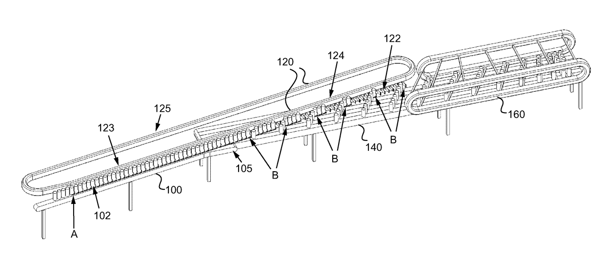
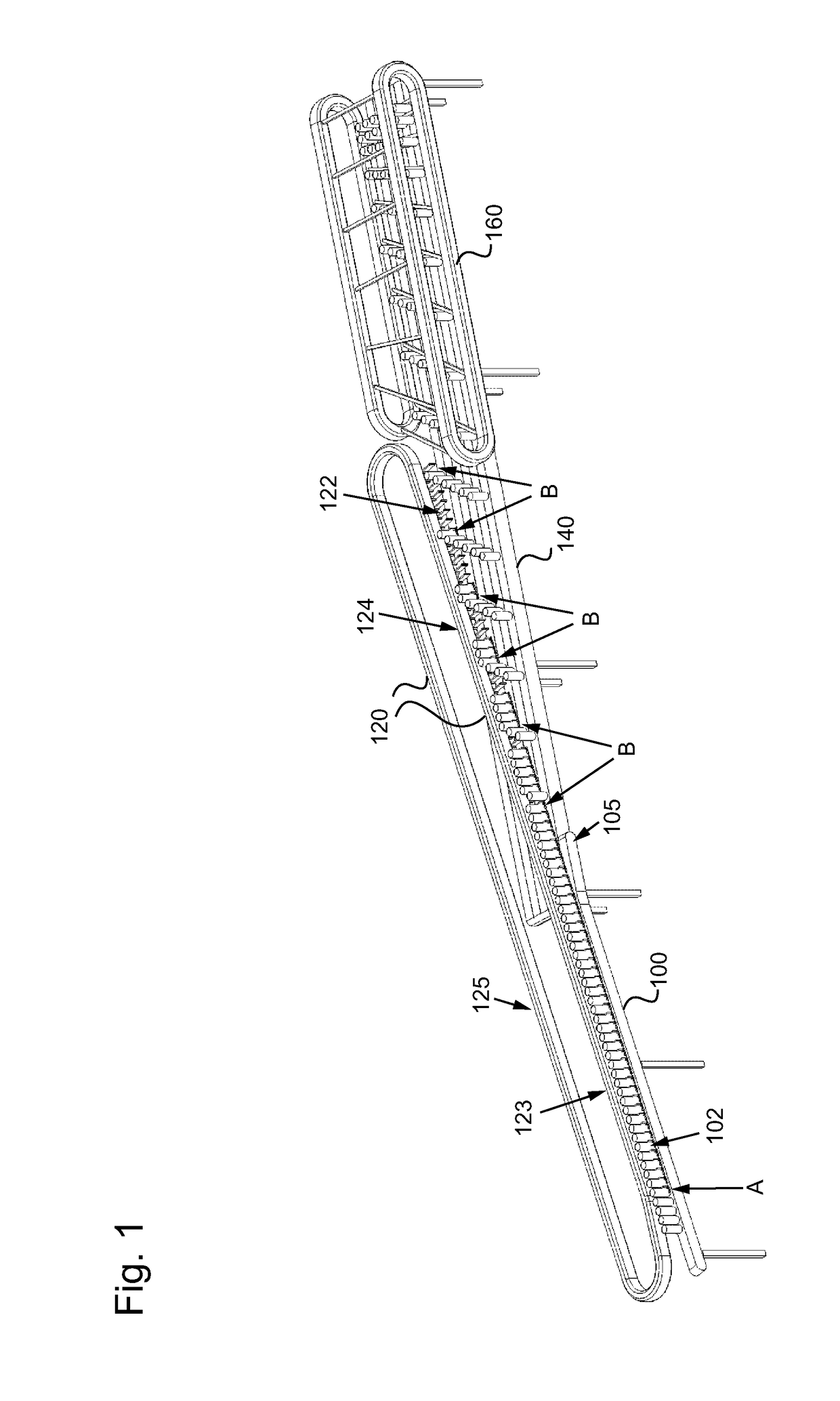
[0006]The above objects are satisfied by a device for distributing and grouping containers in a container treatment assembly, comprising: an infeed conveyor which is configured to convey a plurality of containers in a single-lane infeed flow; an outfeed conveyor which is configured to convey the containers away in multiple lanes; and a transfer conveyor associated with the infeed and the outfeed conveyor and having a plurality of circulating guide elements for the containers; where the transfer conveyor is adapted to separate the containers in a standing position by way of the circulating guide elements from the single-lane infeed flow to the multi-lane outfeed flow by selective guiding, in particular, by pushing them forward and / or decelerating them.

[0007]The containers can be cans, glass bottles or other glass containers with lids, plastic bottles, for example, made of PET, shaped containers such as e.g. rectangular PET containers, containers made of paperboard or the like. In par...


PUM


Abstract

A device for distributing and grouping containers in a container treatment assembly, including an infeed conveyor which is configured to convey a plurality of containers in a single-lane infeed flow; an outfeed conveyor which is configured to convey the containers away in multiple lanes; and a transfer conveyor associated with the infeed and the outfeed conveyor and having a plurality of circulating guide elements for the containers; where the transfer conveyor is adapted to separate the containers in a standing position by way of the circulating guide elements from the single-lane infeed flow to the multi-lane outfeed flow by selective guiding, in particular, by pushing them forward and / or decelerating them.

Description

CROSS-REFERENCE TO RELATED APPLICATION[0001]The present application claims priority to German Patent Application No. 102015203042.3, filed Feb. 20, 2015. The priority application, DE 102015203042.3, is hereby incorporated reference.FIELD OF THE INVENTION[0002]The present invention relates to a device and a method for distributing and grouping containers, in particular bottles, in a container treatment assembly.PRIOR ART[0003]Containers to be treated are in container treatment assemblies, for example, in the beverage industry, often redistributed or regrouped to create, for example, a plurality of parallel container flows or container packs to be processed. Container transport between a labeling machine and a disposable goods packer for producing packs follows, for example, the following procedure: Downstream of the labeling machine, the containers are usually transported in a single row where faulty containers are removed from the container flow. After the containers have been decel...

Claims


Application Information

Patent Timeline
Patent Type & Authority Patents(United States)
IPC IPC(8): B65G47/71B65G47/32B65G54/02B65G15/22B65G19/02B65G19/22B65G47/08B65B21/06B65G47/84
CPCB65G19/02B65G47/088B65G47/32B65G47/841B65G54/02B65G19/22B65G47/715B65B21/06B65G15/22B65G2201/0244B65G47/71
Inventor WALTER, RALFELSPERGER, STEFANNEUBAUER, MICHAEL
Owner KRONES AG
Why Eureka
Try Eureka