Protective cap

a protective cap and membrane technology, applied in the field of protective caps, can solve the problems of high cost, increased increased risk of medical and pharmacological staff being exposed to drugs or solvents which may escape into ambient air, etc., and achieve the effects of increasing friction and/or mechanical engagement, improving the attachment between the membrane and the membrane holder, and reducing the risk of exposur

Active Publication Date: 2018-05-01
CARMEL PHARMA
View PDF26 Cites 9 Cited by
  • Summary
  • Abstract
  • Description
  • Claims
  • Application Information

AI Technical Summary

Benefits of technology

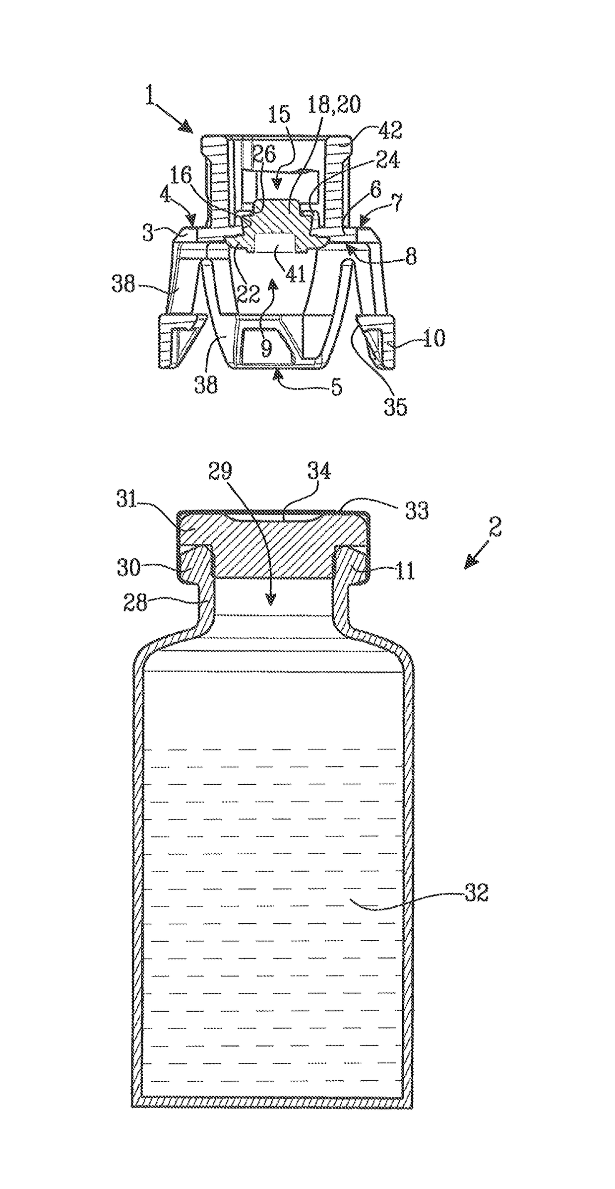
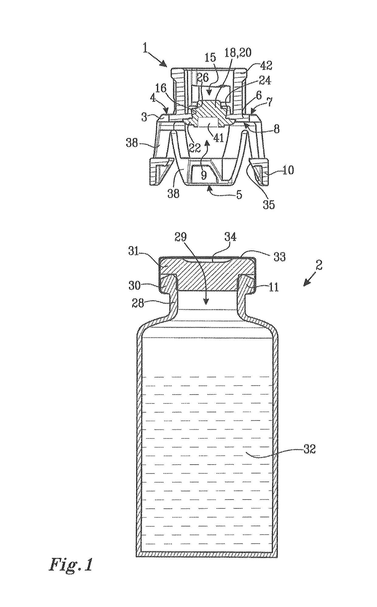
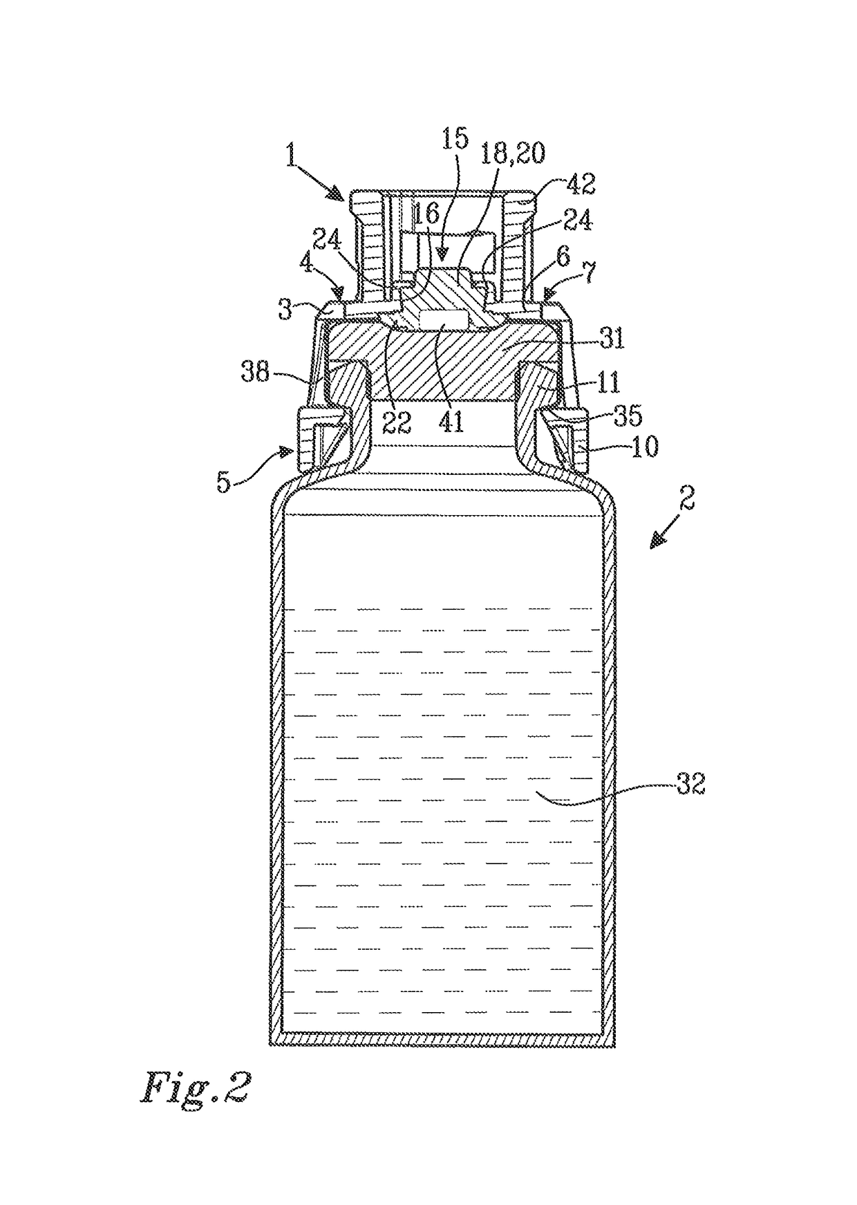
[0015]The resilient membrane of the protective cap is arranged to be pressed into contact with and to form a gasketing, seal against a receiving surface on the medical device. The medical device may be a vial or other type of vessel or container for a liquid substance such as a medicament, a fluid sample or similar. A vial containing a medical liquid is commonly sealed with a cap and a rubber stopper that may be pierced by a needle e.g. for removal of a quantity of the liquid from the vial. “Stoppers” or closures for receptacles are defined by International Standards such as ISO 8362-5 and ISO 8536-2:20110. Upon application of the protective cap of the invention over the sealing cap on the vial and after connecting the protective cap with the vial, the resilient membrane is brought to abut the rubber stopper on the vial and to be sealingly pressed against the rubber stopper. In this manner, a double safety barrier is created at the mouth of the vial. The double barrier may be penetrated by a piercing member and will resiliently close after the piercing member has been retracted from the vial, thus preventing escape of the contents in the vial through the penetration site. At the same time, the gasketing seal between the resilient membrane on the protective cap and the rubber membrane of the vial prohibits sideways leakage of substance which may be released upon retraction of the piercing member.
[0016]The resilient membrane may be held in the membrane holder of the protective cap solely by mechanical forces. Accordingly, the welding step may be omitted, allowing assembly of the protective cap to be made accurately and efficiently at increased speed, without unduly increasing, the number of rejected caps in the process.
[0018]By the term “working tension” as used herein is meant that the resilient membrane is tensioned to a sufficient degree to obtain satisfactory closing of a penetration site after removal of a piercing member but not to a degree where the piercing member will cause permanent damage to the membrane. When held mechanically in the membrane holder, the resilient membrane may be under slight tension in order to keep the membrane from falling out of the membrane holder. However, such “attachment forces” may be very low and are preferably below the forces required to reach the working tension of the membrane. In this manner, the problems with aging and relaxation of the membrane during transport and storage which were found in prior art protective barrier caps may be avoided or at least greatly reduced.
[0019]Accordingly, the working, life of the resilient membrane may be increased as the membrane can be transported and stored in a practically non-tensioned state. The final tensioning in order to achieve a working tension in the resilient, membrane may be accomplished when the protective cap is connected to a medical device as will be further described herein.
[0023]The mechanical holding means may comprise a holding flange surrounding the peripheral edge of the opening in the membrane holder and being arranged at an angle at the outer surface of the end wall of the membrane holder. Accordingly, the holding flange is arranged such that it protrudes from the outer surface of the membrane holder end wall and is inclined towards the opening in the end wall. The resilient membrane is placed with the piercing portion arranged inside the flange such that the size and shape of the piercing portion are defined by the edge of the holding flange. A mechanical holding means of this type may be preferred over the two-part mechanical holders disclosed in WO 2010 / 127691 A1 as they have a simple, yet reliable construction and may be produced with cost efficiency.
[0024]The holding flange serves to keep the resilient membrane from falling out through the opening in the end wall in a direction towards the outer surface of the end wall. In order to keep the membrane in place and restrict its movement in a direction towards the inner surface of the end wall, the membrane may be applied with a slight lateral compression from the sides of the opening in the end wall. Attachment between the membrane and the membrane holder may be further improved by increasing friction and / or mechanical engagement between the membrane and the membrane holder at the opening in the end wall. Such attachment enhancing means may be threads, ridges, spikes or other irregularities in the walls of the opening. Enhanced friction may also be achieved by application of a coating, such as a rubber coating or particle coating on the walls of the opening.

Problems solved by technology

A major problem in relation to drug preparation, drug administration or other similar handling of pharmaceuticals is the risk of medical and pharmacological staff being exposed to drugs or solvents which may escape into ambient air.
The problem is particularly serious when hazardous drugs such as cytotoxics, antiviral drugs, antibiotics and radiopharmaceuticals are concerned.
Other hazards may arise when taking samples relating to virus infections or the like.
However, it has been found that medical devices such as those mentioned above have certain limitations.
Consequently, production of the prior art protective injection devices is complicated and costly.
If the barrier member is too highly tensioned, it may result in the piercing member punching out a piece of the membrane when the membrane is penetrated.
A further problem is that resilient barrier members are subject to aging and may loose some of the production induced tension over time.

Method used


Image

  • Protective cap
  • Protective cap
  • Protective cap

Examples


Embodiment Construction

[0035]FIG. 1 shows a protective cap 1 and a medical device in the form of a vial 2. The protective cap 1 comprises a membrane holder 3 having a first end 4 with an end wall 6. The end wall 6 has an outer surface 7 and an inner surface 8. A second end 5 is arranged at a distance from the first end 4 and is provided with an end opening 9. The second end 5 is arranged to be connected to the vial 2 and is provided with first connection means 10 placed at the periphery of the end opening 9 and intended to engage with cooperating second connection means 11 on the vial 2.

[0036]The end wall 6 of the membrane holder 3 is provided with a central piercing opening 15. The piercing opening 15 has a peripheral edge 16. A resilient membrane 18 is arranged to cover the piercing opening 15. The resilient membrane 18 has a piercing portion 20 and a sealing portion 22 peripherally surrounding the piercing portion 20.

[0037]The resilient membrane 18 is attached to the membrane holder 3 by mechanical hol...


PUM


Abstract

A protective cap (1) for application on a medical device such as a medical vial (2) comprising a membrane holder (3) in which a resilient membrane (18) is mounted. The protective cap (1) is provided with connection means (10) for connecting the cap (1) to the medical device (2). The resilient membrane (18) comprises a piercing portion (20) and a sealing portion (22) and is mechanically and / or adhesively held in the protective cap (1) and is arranged to be brought into sealing contact with a receiving portion of the medical device (2) when the protective cap (1) is applied on the medical device (2).

Description

CROSS-REFERENCE TO RELATED APPLICATIONS[0001]This application is the United States national phase of International Application No. PCT / SE2012 / 050546 filed May 21, 2012, the disclosure of which is hereby incorporated in its entirety by reference.TECHNICAL FIELD[0002]The invention relates to a protective cap for application on a medical device such as a medical vial, said protective cap comprising a membrane holder having a first end with an end wall, said end wall having an outer surface and an inner surface and a second end at a distance from said first end said second end being adapted to be placed over a receiving portion of said medical device and being provided with connection means for connecting said protective cap to said medical device.BACKGROUND OF THE INVENTION[0003]A major problem in relation to drug preparation, drug administration or other similar handling of pharmaceuticals is the risk of medical and pharmacological staff being exposed to drugs or solvents which may es...

Claims


Application Information

Patent Timeline
Patent Type & Authority Patents(United States)
IPC IPC(8): A61J1/00A61J1/14A61M39/04B65D51/00A61J1/05
CPCA61J1/1406A61J1/1412A61M39/04B65D51/002A61J1/1425A61J1/05
Inventor OHLIN, GUNNAR
Owner CARMEL PHARMA
Why Eureka
Try Eureka