Cargo bay construction with a slideable wall and vehicle with such a cargo bay construction

a technology of cargo bay and construction, which is applied in the direction of vehicle with pusher plate, transportation items, load transportation vehicles, etc., can solve the problems of increasing the construction cost of this type of covering of the opening of the channel, and increasing the maintenance cost of the vehicle, so as to achieve the effect of low construction cost, low driving power required for sliding the wall, and low cost of the cargo bay construction

Active Publication Date: 2018-05-01
FLIEGL SR JOSEF
View PDF11 Cites 1 Cited by
  • Summary
  • Abstract
  • Description
  • Claims
  • Application Information

AI Technical Summary

Benefits of technology

[0010]The underlying thought of the invention is to replace the belt, which is susceptible to wear and is consequentially unstable and requires a tension guide, with a stable but elastic deformable cover that does not require a tension guide and still provides a secure cover of the channel opening through the elastic deformability However in addition to this, a local lift from the floor of the cargo bay construction is made possible.
[0014]An appropriate cover for an inventive cargo bay construction can be cheaply developed from sheet metal, particularly sheet steel. Such a cover is characterized also through a relatively good resistance to wear.
[0017]The sliding of the wall can preferably be designed so that the drive slide moves by means of a drive mechanism and is consequently integrated into this. For this, a drive mechanism can be designed with a closed revolving mechanism whereby the drive slides are solidly connected with a section of the mechanism. It is however preferably designed so that the mechanism is open and thus developed with two ends, whereby the drive slides are connected with both ends of the mechanism. This design in particular can make a constructive advantageous integration of a tension guide for the mechanism possible, which is arranged between the drive slides and at least one of the mechanisms. Such a tension guide can be especially advantageously developed as a simple spring element or even a coil spring that is preloaded and supported between the corresponding end of the mechanism and the drive mechanism.
[0018]Depending on the selection of the material for the cover, the scope within which this is elastic and deformable, can be limited. It is therefore preferably designed in the inventive cargo bay construction that the drive mechanism encompasses a statically integrated mobile drive motor into the cargo bay construction and consequently not into the front wall that for instance can be developed electrically, hydraulically or pneumatically. This can be avoided (differently from the DE 20 2004 009 744 U1 known cargo bay construction) by the cover being led over at least a relatively large drive wheel, and therefore having to be raised correspondingly far from the floor. Additionally, the static integration of the drive motor still exhibits the advantage that the mass of the slideable wall, and with it the driving power required for sliding the wall, is kept low. And eventually it is no longer necessary to have supply lines that are supplied with energy from the drive motor, so to develop this so that the mobility of the drive motor with the front wall is allowed. Through this the construction costs for the cargo bay construction are kept low.
[0019]In an additionally preferred design of the inventive cargo bay construction it can be designed so that the drive mechanism exhibits a chain section cooperatively with the drive motor as well as a cable section. The design of the mechanism is made possible by this so that in the corresponding design of the drive mechanism in the back and forth sliding of the mechanism, no complete rotation of the mechanism is required, so that the development of the mechanism as with the drive motor cooperating chain on this section can be restricted, that also is led in the possible movement of the slideable wall over the driver motor and in particular a drive sprocket of the drive motor. The other sections of the mechanism can by contrast be led out as a simple cable, that can represent a cost effective construction, that can moreover be distinguished through a low weight and where applicable also have a reduced operation noise.
[0021]In an additional preferred design of the inventive cargo bay construction, it can still be designed so that the drive slide is arranged within one of the developed channels spanning the floor (and thereby developed as a drop from a main surface of the floor). Particularly preferred in this channel; the drive mechanism can also be partially or totally arranged. Through this, the need to preserve a large construction space for the drive of the slideable wall below the floor can be avoided. The channel spanning the cargo bay is decreased in this process as is the storage volume of the storage space, which however takes place in an merely comparatively low scope and therefore can be seen as negligible.

Problems solved by technology

On the one hand, a cost effective producible belt is relatively susceptible to wear so that this needs to be relatively frequently changed out in connection with the impacting cargo in the cargo bay on the belt.
This increases the maintenance costs for the vehicle.
In addition to this, the construction costs for this type of covering of the opening of the channel are also relatively high, which can be traced back to the necessary tension guide for the belt.

Method used


Image

  • Cargo bay construction with a slideable wall and vehicle with such a cargo bay construction
  • Cargo bay construction with a slideable wall and vehicle with such a cargo bay construction
  • Cargo bay construction with a slideable wall and vehicle with such a cargo bay construction

Examples


Embodiment Construction

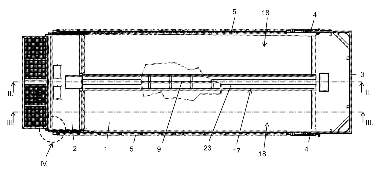
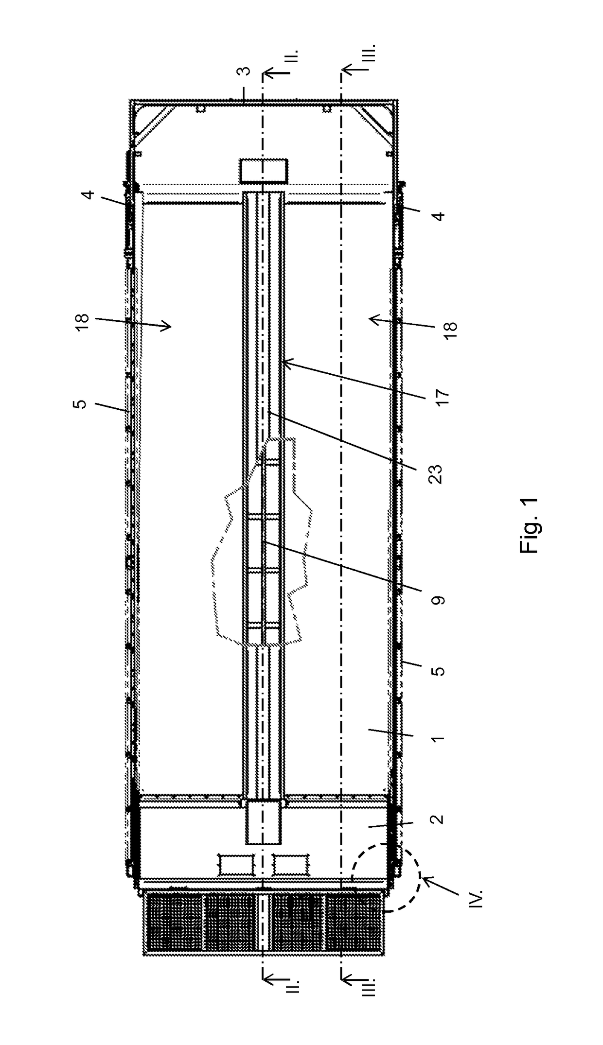
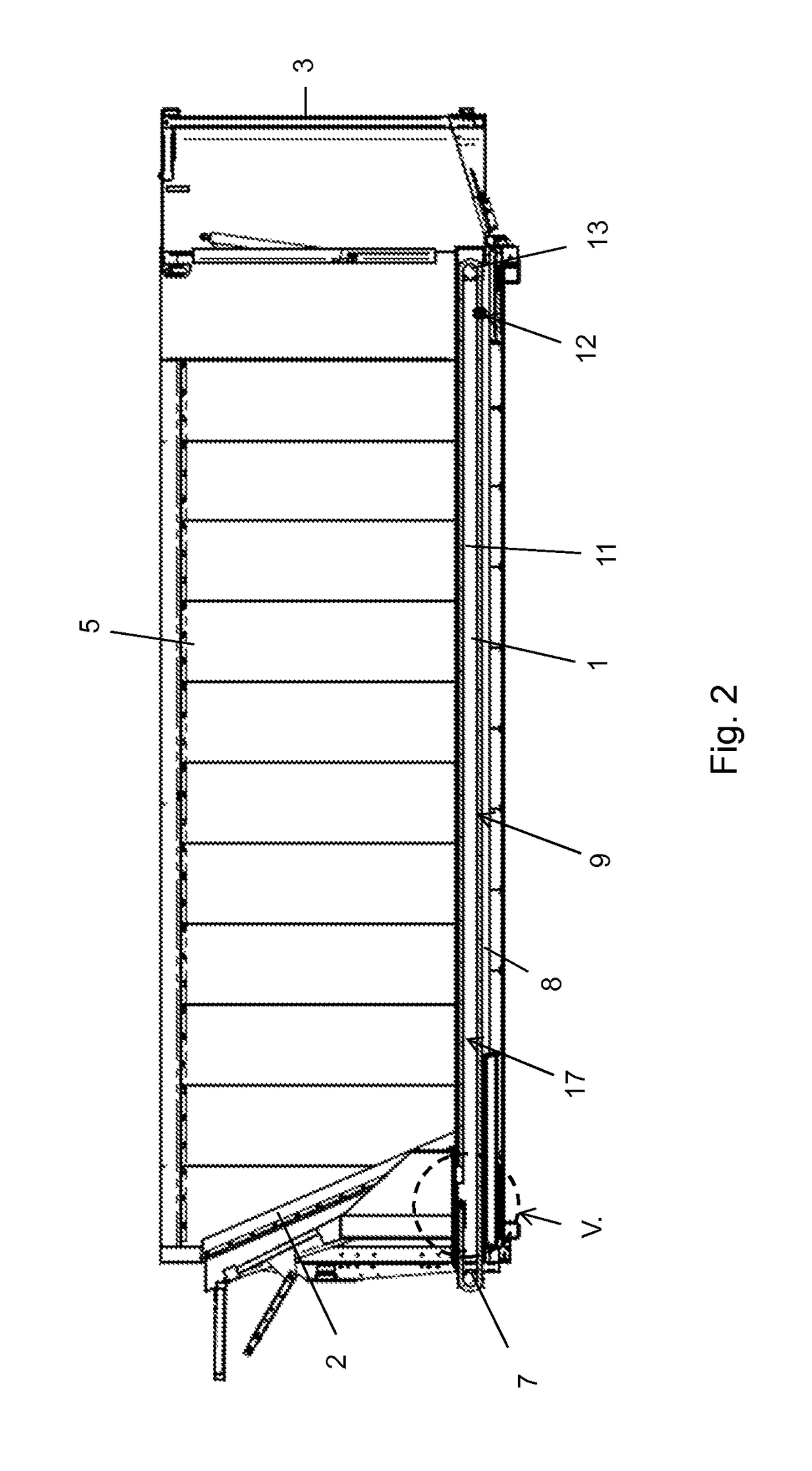
[0033]The cargo bay construction represented in the drawings encompasses a floor 1, as well as the adjacent walls at the end of the floor 1, that limit the upwardly open cargo bay. It is seen in a longitudinal direction of the cargo bay construction, that an anterior front wall 2 is moved by being slid, while a back wall 3 is moved upwardly on hinges of the swivel joints 4, in order to provide unloading openings. Additionally, two fixed walls 5 are still designed.

[0034]The front wall 2 is moved by being slid on the floor 1 along the longitudinal direction of the cargo bay construction, whereby the volume of the cargo bay can be changed. This can then be used to unload a stored load in the cargo bay from the opened back wall 3 over the unloading opening, which in comparison to tip troughs, can take place relatively constantly. The load can be sealed through the sliding of the front wall 2, which can be particularly designed for the closed back wall 3. FIGS. 1 to 3 show the front wall...


PUM


Abstract

A cargo bay construction includes a floor and a wall that is slideable along the floor, whereby, below the wall facing surfaces of the floor, a drive slide is arranged and is connected with the wall that is slideable along the floor over a developed guide opening in the floor, characterized in that the guide opening is covered by an elastic deformable cover overlying the floor, whereby the cover in the area of the drive slide is lifted from the floor under elastic deformation.

Description

CROSS-REFERENCE TO RELATED APPLICATIONS[0001]This application claims priority from German Application No. 20 2014 102 305.4, filed May 16, 2014, the disclosure of which is incorporated herein by reference.FIELD OF INVENTION[0002]The invention concerns a cargo bay construction with a slideable wall, and a vehicle with this type of cargo bay construction.BACKGROUND OF THE INVENTION[0003]The sliding of the wall in this type of cargo bay construction serves the purpose of making the limited cargo bay to the side of the wall temporarily smaller in order to either unload the cargo stored in the cargo bay over an unloading opening located opposite a normally slideable wall or in order to compress the load in the completely closed cargo bay.[0004]A trailer with an appropriate cargo bay construction is known from the DE 20 2004 009 744 U1. There, the cargo bay, which opens from the top, is distinguished from a cargo bay floor, a moveable front wall, a back wall that is opened by being folded...

Claims


Application Information

Patent Timeline
Patent Type & Authority Patents(United States)
IPC IPC(8): B62D63/06B60R5/04B62D63/08B60P1/00
CPCB62D63/061B62D63/08B60R5/04B60P1/006
Inventor FLIEGL, SR., JOSEF
Owner FLIEGL SR JOSEF
Why Eureka
Try Eureka