Iterative image reconstruction with a sharpness driven regularization parameter

a regularization parameter and image reconstruction technology, applied in image enhancement, tomography, instruments, etc., can solve problems such as introduction of artifacts and/or incorrect quantitative values

Active Publication Date: 2018-05-01
KONINKLJIJKE PHILIPS NV
View PDF9 Cites 19 Cited by
  • Summary
  • Abstract
  • Description
  • Claims
  • Application Information

AI Technical Summary

Benefits of technology

[0007]Aspects described herein address the above-referenced problems and others.

Problems solved by technology

With the above iterative image reconstruction formulation, the spectral images may have similar noise; however, there is no guarantee that they will have a similar spatial resolution, and, unfortunately, a linear combination of spectral images having different spatial resolution may introduce artifact and / or have incorrect quantitative values.

Method used


Image

  • Iterative image reconstruction with a sharpness driven regularization parameter
  • Iterative image reconstruction with a sharpness driven regularization parameter
  • Iterative image reconstruction with a sharpness driven regularization parameter

Examples


Embodiment Construction

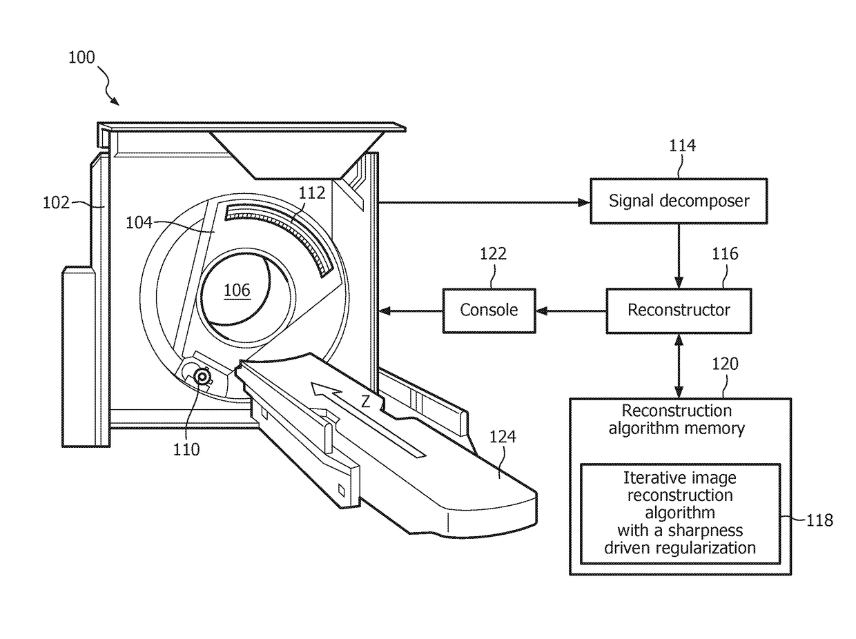
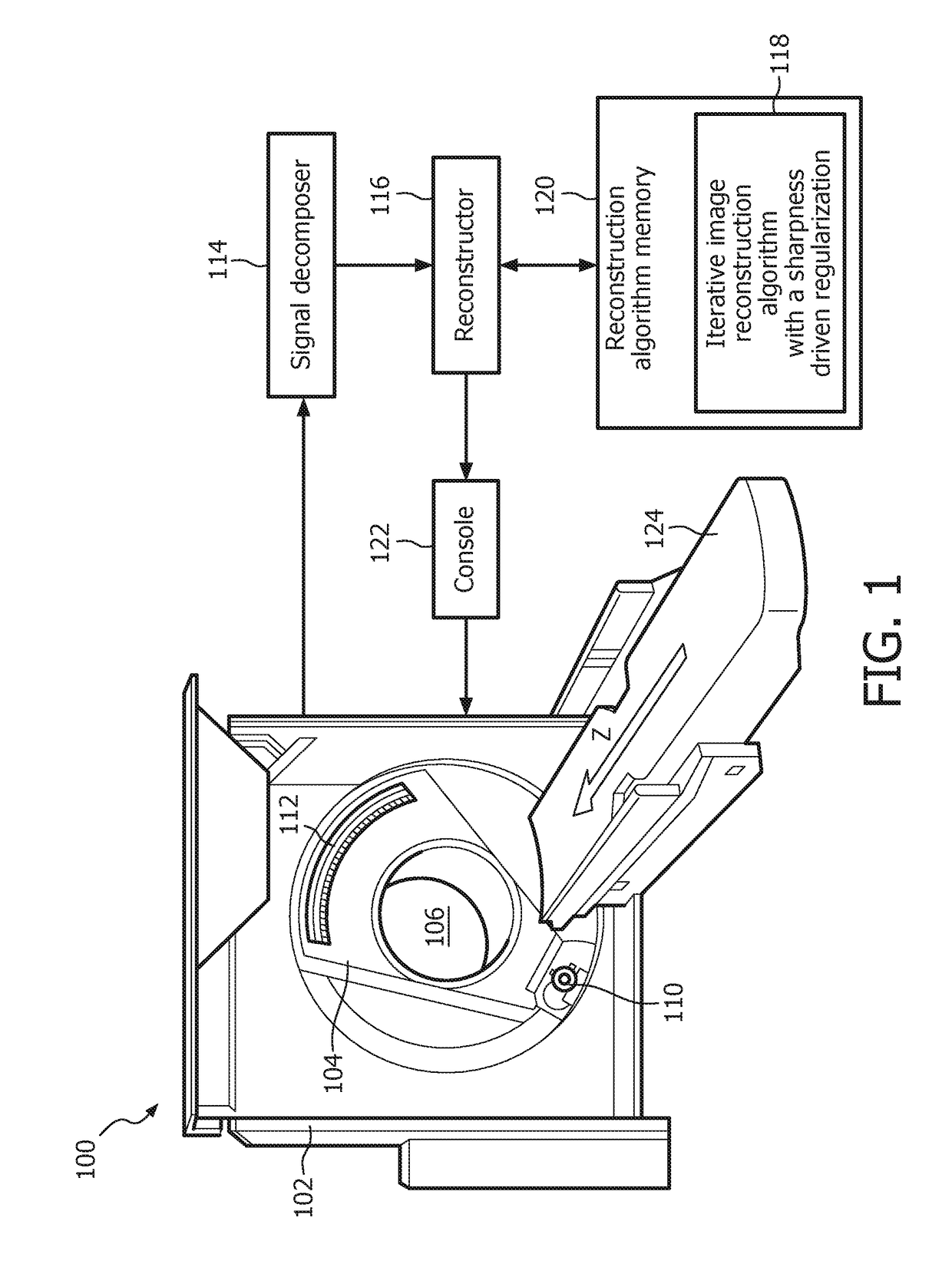
[0017]FIG. 1 illustrates an example imaging system 100 such as a computed tomography (CT) system.

[0018]The imaging system 100 includes a stationary gantry 102 and a rotating gantry 104, which is rotatably supported by the stationary gantry 102. The rotating gantry 104 rotates around an examination region 106 about a longitudinal or z-axis “Z”.

[0019]A radiation source 110, such as an x-ray tube, is rotatably supported by the rotating gantry 104, rotates with the rotating gantry 104, and emits x-ray radiation that traverses the examination region 106. In one instance, the radiation source 110 is configured to switch an emission voltage between two or more emission voltages (e.g., 80 and 140 kVp, 100 and 120 kVp, etc.) within an integration period and / or otherwise. In a variation, the imaging system 100 includes multiple radiation sources 110 that emit radiation at different emission voltages. In another variation, the radiation source 110 includes a single broad spectrum x-ray tube.

[0...


PUM


Abstract

A method includes performing a first pass of an iterative image reconstruction in which an intermediate first spectral image and an intermediate second spectral image are generated using an iterative image reconstruction algorithm, start first spectral and second spectral images, and initial first spectral regularization and second spectral regularization parameters, updating at least one of the initial first spectral regularization or second spectral regularization parameters, thereby creating an updated first spectral regularization or second spectral regularization parameter, based at least on a sharpness of one of the intermediate first spectral or second spectral images, and performing a subsequent pass of the iterative image reconstruction in which an updated intermediate first spectral and second spectral image is generated using the iterative image reconstruction algorithm, the intermediate first spectral and second spectral images, and the updated first spectral regularization and Compton scatter regularization parameters.

Description

CROSS REFERENCE TO RELATED APPLICATIONS[0001]This application is the U.S. National Phase application under 35 U.S.C. § 371 of International Application No. PCT / IB2015 / 057072, filed Sep. 15, 2015, published as WO 2016 / 042466 on Mar. 24, 2016, which claims the benefit of U.S. Provisional Patent Application No. 62 / 050,402 filed Sep. 15, 2014. These applications are hereby incorporated by reference herein.FIELD OF THE INVENTION[0002]The following generally relates to iterative image reconstruction with a sharpness driven regularization and finds particular application to computed tomography (CT). The following is also amenable to other imaging modalities.BACKGROUND OF THE INVENTION[0003]A CT scanner includes an x-ray tube mounted on a rotatable gantry that rotates around an examination region about a z-axis. A detector array subtends an angular arc opposite the examination region from the x-ray tube. The x-ray tube emits radiation that traverses the examination region. The detector arra...

Claims


Application Information

Patent Timeline
Patent Type & Authority Patents(United States)
IPC IPC(8): G06K9/00G06T11/60A61B6/03G06K9/62G06T5/50G06T7/00G06T11/00A61B6/00
CPCG06T11/008A61B6/032A61B6/5235A61B6/5282G06K9/6215G06T7/0012G06T11/60G06T5/50G06T2211/424G06T2207/10081G06T2207/30004G06T11/006G06T2211/408G06F18/22
Inventor KOEHLER, THOMASPROKSA, ROLANDGRASS, MICHAEL
Owner KONINKLJIJKE PHILIPS NV
Why Eureka
Try Eureka