Variable adjustment for precise matching of multiple chamber cavity housings

a technology of cavity housing and variable adjustment, which is applied in the direction of semiconductor/solid-state device manufacturing, basic electric elements, electric devices, etc., can solve the problems of increasing the cost of maintenance of each individual lift mechanism, and affecting the efficiency of the individual lift mechanism

Active Publication Date: 2018-05-01
ASM IP HLDG BV
View PDF1333 Cites 339 Cited by
  • Summary
  • Abstract
  • Description
  • Claims
  • Application Information

AI Technical Summary

Problems solved by technology

However, multiple individual wafer lift mechanisms have a disadvantage as each individual lift mechanism incurs significant capital costs.
In addition, the cost may rise due to maintenance of each individual wafer lift mechanism.
Individual lifts have the following additional disadvantages: (1) More complex software checks are required for motion to occur, slowing throughput; (2) Imprecise motion matching due to manufacturing variances and tolerance stack-ups; (3) Component stack-up due to multiple identical parts requirements and the supporting cables / hoses required for actuation; (4) Multiplied opportunities for sensor failure with a lack of system redundancy (a ‘master’ lift assembly can have multiple redundant sensors if needed and can be easily recovered from a motion sensor error); and (5) Longer system down-time during maintenance due to repetitive setups being required for each chamber and its motion system.
While it may be possible to have individual wafer lift mechanisms for each cavity, the cost issues described above and potential spacing issues may not make this feasible.
These same methods were not as suited for Chemical Vapor Deposition (CVD) and its variant methods including Plasma-enhanced CVD (PECVD) and Atomic Layer Deposition (ALD).
In addition, for multiple cavity systems, another issue with multiple individual wafer lift mechanisms is the reproducibility of reaction conditions.
Merely disposing two wafer holders for two cavities on a single wafer lift mechanism may be insufficient because discrepancies with the vertical positions of the two wafer holders may exist as a result of a tolerance stack-up.
This could potentially lead to defects in manufacturing, as well as decreased chamber life due to deposition material ‘leakage’ into non-process regions of the chamber.

Method used


Image

  • Variable adjustment for precise matching of multiple chamber cavity housings
  • Variable adjustment for precise matching of multiple chamber cavity housings
  • Variable adjustment for precise matching of multiple chamber cavity housings

Examples


Embodiment Construction

[0025]Although certain embodiments and examples are disclosed below, it will be understood by those in the art that the invention extends beyond the specifically disclosed embodiments and / or uses of the invention and obvious modifications and equivalents thereof. Thus, it is intended that the scope of the invention disclosed should not be limited by the particular disclosed embodiments described below.

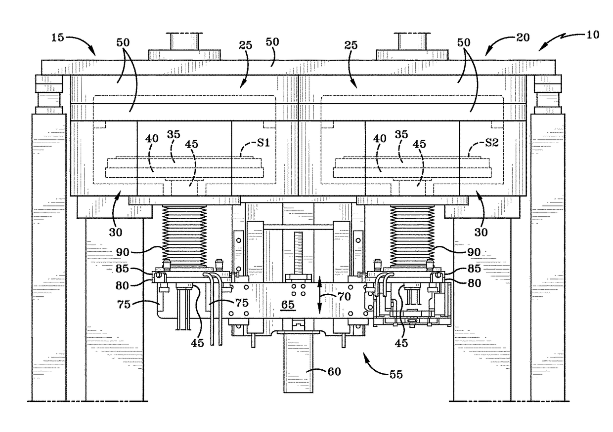
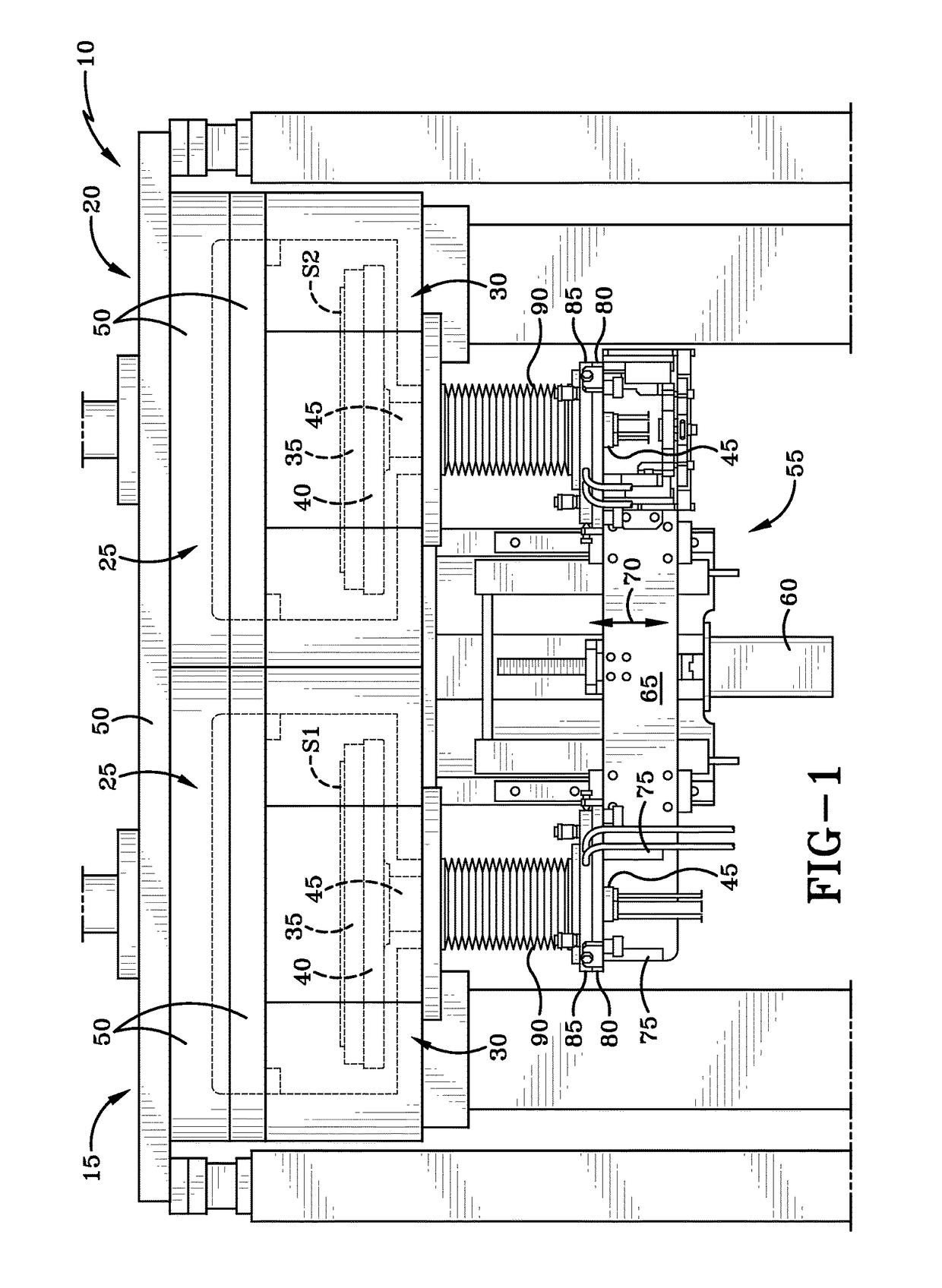
[0026]FIG. 1 illustrates a reaction system 10 according to at least one embodiment of the invention. The reaction system 10 includes a first reaction cavity 15 and a second reaction cavity 20. The first reaction cavity 15 and the second reaction cavity 20 may comprise of separate chambers or of a single chamber with a divider. The first reaction cavity 15 and the second reaction cavity 20 each comprise an upper portion 25 and a lower portion 30.

[0027]Substrate S1, S2 may be loaded onto a susceptor 35 when the susceptor 35 is positioned in the lower portion 30. The susceptor 35 also inc...


PUM


Abstract

A vertical adjustment assembly is disclosed in order to provide for matching vertical positions of two substrates within separate chambers or cavities of a reaction system for processing of semiconductor substrates. The vertical adjustment assembly, in cooperation with a main lift driver, can provide for a more accurate positioning of the substrates to account for a tolerance stack-up error.

Description

FIELD OF INVENTION[0001]The invention relates to a multiple-chambered reaction system for processing semiconductor substrates. Specifically, the invention relates to a vertical adjustment component of the reaction system to allow for precise matching of wafer processes within different chambers.BACKGROUND OF THE DISCLOSURE[0002]Assemblies in reaction chambers generally may allow for lateral adjustment and leveling of a wafer lift mechanism. A wafer is disposed on a wafer holder, which may have a heating element. The lateral adjustment allows for horizontal centering of a wafer within the reaction chamber. The lateral adjustment takes place by using independent x-y adjustment block assemblies. For systems with multiple reaction chambers, the lateral adjustment is duplicated for each reaction chamber to center and level the wafer holder.[0003]With respect to leveling of the wafer lift mechanism, leveling ensures that a wafer disposed on the wafer lift mechanism is as flat as possible ...

Claims


Application Information

Patent Timeline
Patent Type & Authority Patents(United States)
IPC IPC(8): H01L21/687H01L21/68
CPCH01L21/68742H01L21/68792H01L21/68785H01L21/68H01L21/67092H01L21/67098H01L21/67155H01L21/687
Inventor COOMER, STEPHEN DALE
Owner ASM IP HLDG BV
Why Eureka
Try Eureka