Microphone stand adjusting structure

a technology of adjusting structure and microphone stand, which is applied in the direction of stand/trestle, electrical transducer, electrical apparatus, etc., can solve the problems of difficult to be used in important occasions or performances, the inner tube being extended from or inserted into the outer tube is usually not smooth upon the extension or contraction adjustment, and the inability to use the tripod, etc., to achieve convenient use, practicality and security.

Active Publication Date: 2018-05-01
GAO FONG IND
View PDF16 Cites 4 Cited by
  • Summary
  • Abstract
  • Description
  • Claims
  • Application Information

AI Technical Summary

Benefits of technology

[0004]The main object of the present invention is to provide a microphone stand structure, allowing an upper frame rod to be elevated automatically and adjusted, extended to a proper elevation, after a locking seat is released, by an extensible pressure rod arranged in a hollow main frame rod, and the whole stand height can be fixed simply by locking the locking seat, thereby achieving the convenience, practicality and security of microphone placement and stand adjustment.

Problems solved by technology

However, since the structure thereof are too simple and the assembled stand is too long, the inner tube being extended from or inserted into the outer tube usually is not smooth upon the extension or contraction adjustment.
Especially, longer insertion assembly will cause shaking such that it is difficult to be used in important occasions or performances.
However, the locking and releasing operations thereof are very minute and complicated upon adjustment such that it is not possible for the tripod to be adjusted in the middle of a performance; it may be a secure design, but not suitable for use in a performance in which the placement height of a microphone is always needed to change timely according to the heights and postures of performers.

Method used


Image

  • Microphone stand adjusting structure
  • Microphone stand adjusting structure
  • Microphone stand adjusting structure

Examples


Embodiment Construction

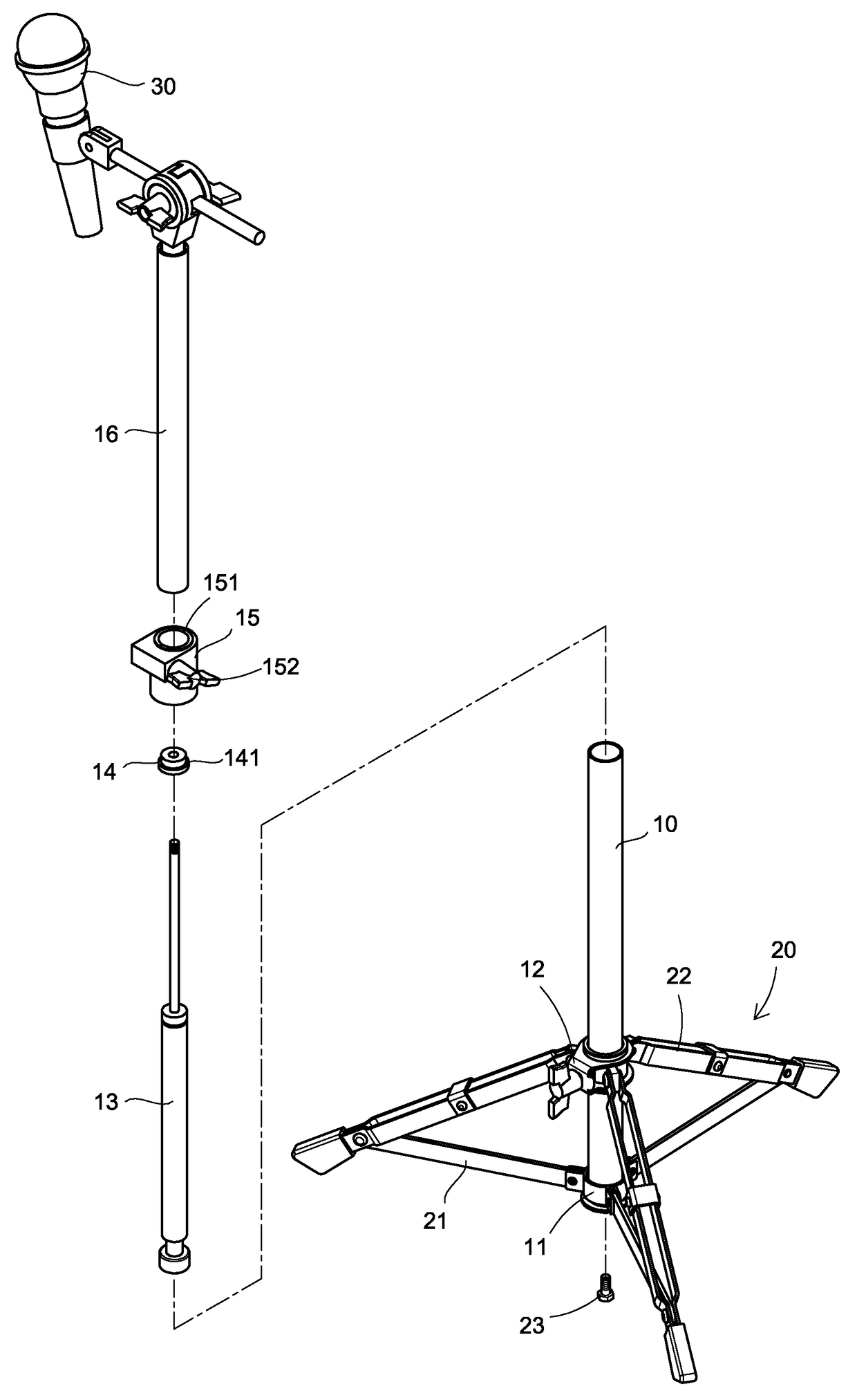
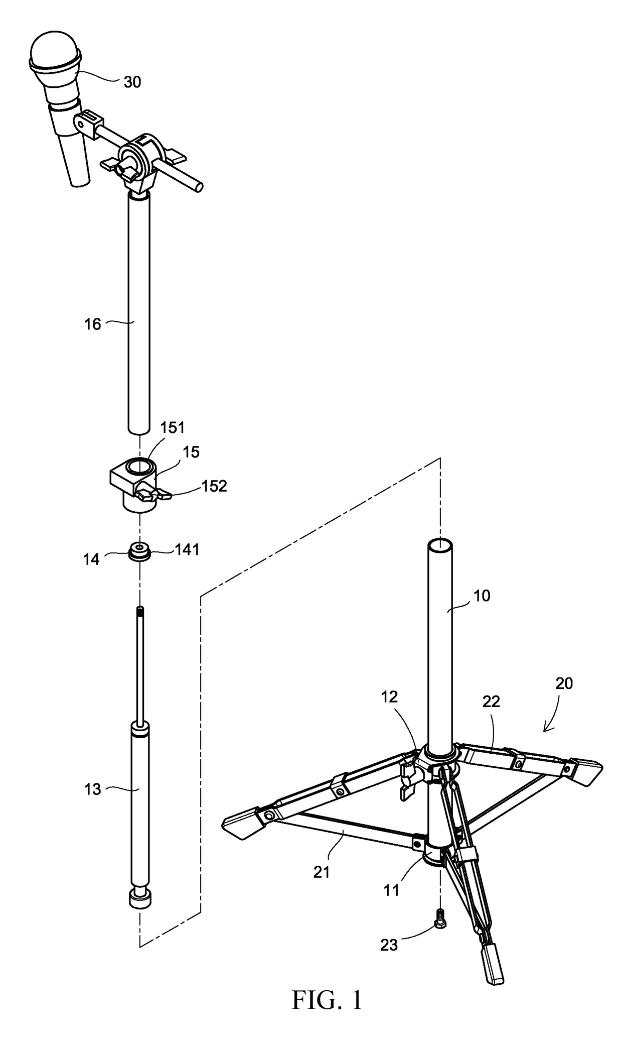
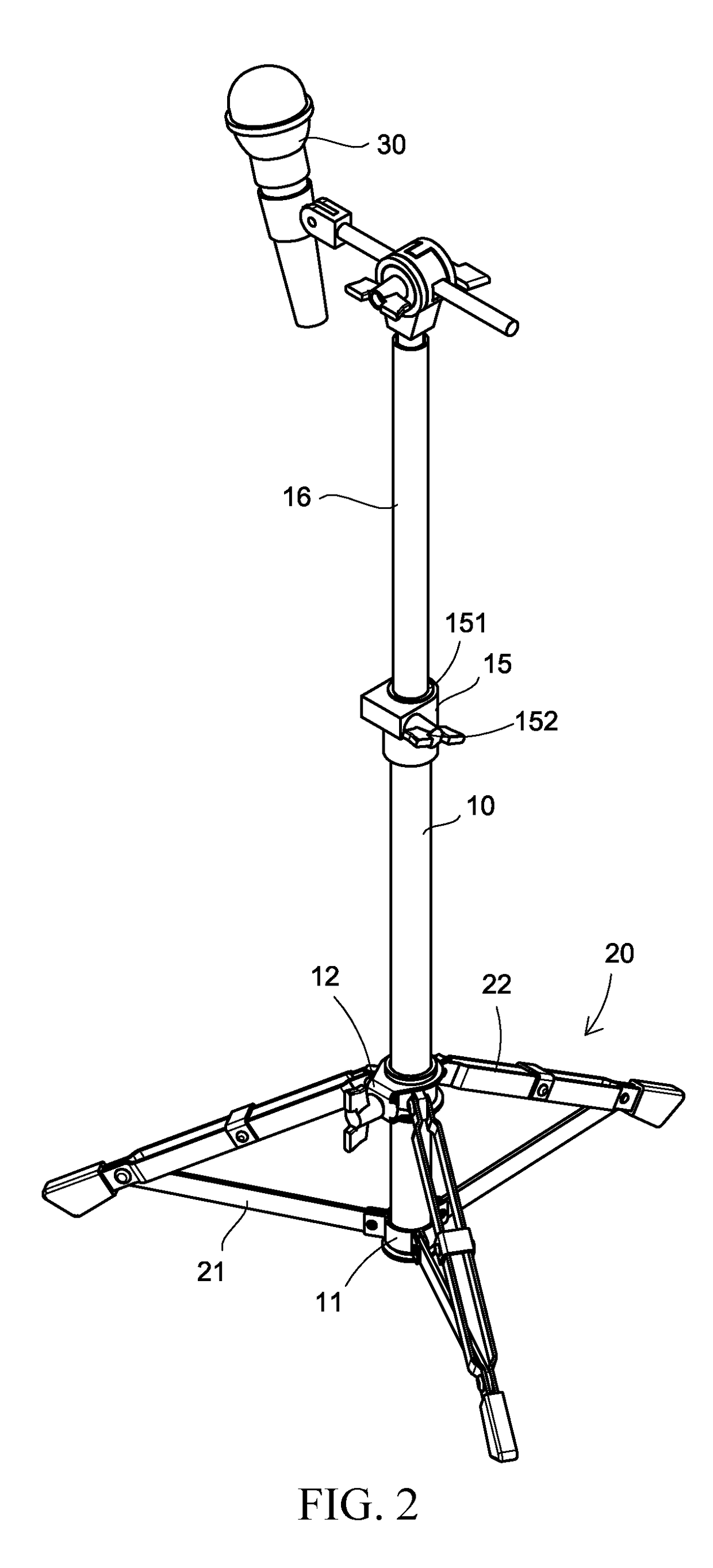
[0009]The present invention is a microphone stand adjusting structure, mainly setting a support stand for the placement and use of a microphone into two-part telescopically adjustable structure. Referring to FIGS. 1 to 4, the structure includes: a hollow tubular main frame rod 10; and a tripod set 20, adapted to support collapsible operating frames and locked to the bottom of the main frame rod 10, and having collapsible enforced linkages 21 in connection with the peripheral of a central base 11 and in equal connection with respective tripod rods 22, where ends of the tripod rods 22 are respectively coupled pivotally equally to the outer peripheral of the fixing seat ring 12, thereby allowing the collapsing operation of the tripod set 20. Furthermore, the hollow main frame rod 10 extends through the fixing seat ring 12 to insert in and assemble on the central base 11, thereby being locked and connected integrally thereto. Thereupon, the collapsing angle of the supporting tripod can ...


PUM


Abstract

A microphone stand structure allows an upper frame rod to be elevated automatically for adjustment to a proper elevation after a locking seat is released. A pressure rod is received and mounted in a hollow main frame rod and includes an extensible member having a top end supporting a bottom end of the upper frame rod movably inserted into the hollow main frame rod such that the whole stand height can be selectively fixed simply locking the locking seat.

Description

TECHNICAL FIELD OF THE INVENTION[0001]The present invention relates to a microphone stand adjusting structure, and more particularly to a microphone stand lifting structure capable of the convenient placement of a microphone and the arbitrary adjustment of the height thereof.DESCRIPTION OF THE PRIOR ART[0002]Conventional microphone stands are generally divided into single tube typed stand and double tube typed stand constituted by a upper tube inserted in a lower tube and being extensible to change an assembly height, the latter being more popular. The double tube typed stands are configured with a fixing seat in the middle thereof for the locking upon the extension or contraction adjustment thereof so as to adjust the height of the whole stand, thereby to be in response to a user's height so as to achieve sound receiving convenience and sound effect assurance. However, since the structure thereof are too simple and the assembled stand is too long, the inner tube being extended from...

Claims


Application Information

Patent Timeline
Patent Type & Authority Patents(United States)
IPC IPC(8): F16M11/24H04R1/02F16M11/18F16M11/28
CPCH04R1/02F16M11/18F16M11/28F16M11/245H04R2201/025F16M2200/027F16M11/10F16M11/2021F16M2200/022
Inventor LIAO, CHI-CHING
Owner GAO FONG IND
Why Eureka
Try Eureka