Cutter adapted to be held by human hand or finger

a technology of hand or finger, which is applied in the field of cutting devices, can solve the problems of limited cutting range of materials, device limitations, and breadth of material that prior art cutters can cut, and achieve the effects of convenient use, safety, accuracy and speed, and comfort of holding

Inactive Publication Date: 2007-01-11
SHURTECH BRANDS
View PDF32 Cites 3 Cited by
  • Summary
  • Abstract
  • Description
  • Claims
  • Application Information

AI Technical Summary

Benefits of technology

[0004] The present invention sets forth multiple novel improvements to the art of cutting devices that slide over or are supported by a human finger. These improvements primarily involve the safety, convenience, accuracy, and speed with which various types of material may be cut. The cutter invention described herein is a device that is comfortable to hold, simple to use, and capable of making quick and accurate cuts.
[0005] In one embodiment, the cutter device invention includes a generally cylindrical inner sleeve slideably engaged with a generally cylindrical outer sleeve, where each sleeve includes an open end and a closed end. The open end of the inner sleeve is adapted to fit over a human finger. The inner sleeve has an extended position and a retracted position with respect to the outer sleeve. A blade for cutting various materials is attached to the closed end of the inner sleeve. When the inner sleeve is in the extended position, the blade protrudes through a slot in the closed end of the outer sleeve thus permitting the user to bring the blade into contact with the material to be cut. A button is formed from the inner sleeve material resembling a tab and is bent slightly in an outward radial direction. A button aperture is disposed along the outer sleeve such that when the inner sleeve is in the extended position, the button is aligned with and engages the button aperture. A biasing element is confined between the sleeves and is disposed about the blade. When the button is pushed inward it disengages from the button aperture and the biasing element urges the inner sleeve into the retracted position. The inner sleeve further includes a pair of retaining ribs which project radially outward and engage a pair of retaining rib apertures in the outer sleeve. The retaining ribs prevent the inner sleeve from becoming disengaged with the outer sleeve. Lastly, the closed end of the outer sleeve includes a plurality of flat guide surfaces and a straight guide groove. A pair of the flat guide surfaces intersect at about a 90° angle to permit the cutter device to accurately cut material along an inside corner of an object. A large flat guide surface serves to maintain the blade at a fixed angle with the material to be cut permitting the user to make smooth straight cuts. Finally, the straight guide groove permits the user of the cutter device to make straight and accurate cuts along the edge of a support surface by gliding the straight guide groove along the edge of the support surface.

Problems solved by technology

However, these devices have a number of limitations.
One limitation involves the breadth of material that prior art cutters can cut.
In most cases, the prior art cutters are capable of cutting only a limited range of materials (e.g. grape stems or envelopes).
Another limitation involves the ergonomic and safety aspects of the prior art cutters.
Many prior art devices use an exposed fixed blade design which can lead to severe cuts if the user is not extremely careful at all times. In addition, other prior art devices attach to the user's hand in a manner that may result in fatigue and discomfort after extended use.
Further limitations of the prior art cutters involve their ability to make straight, smooth, and consistent cuts.

Method used


Image

  • Cutter adapted to be held by human hand or finger
  • Cutter adapted to be held by human hand or finger
  • Cutter adapted to be held by human hand or finger

Examples


Embodiment Construction

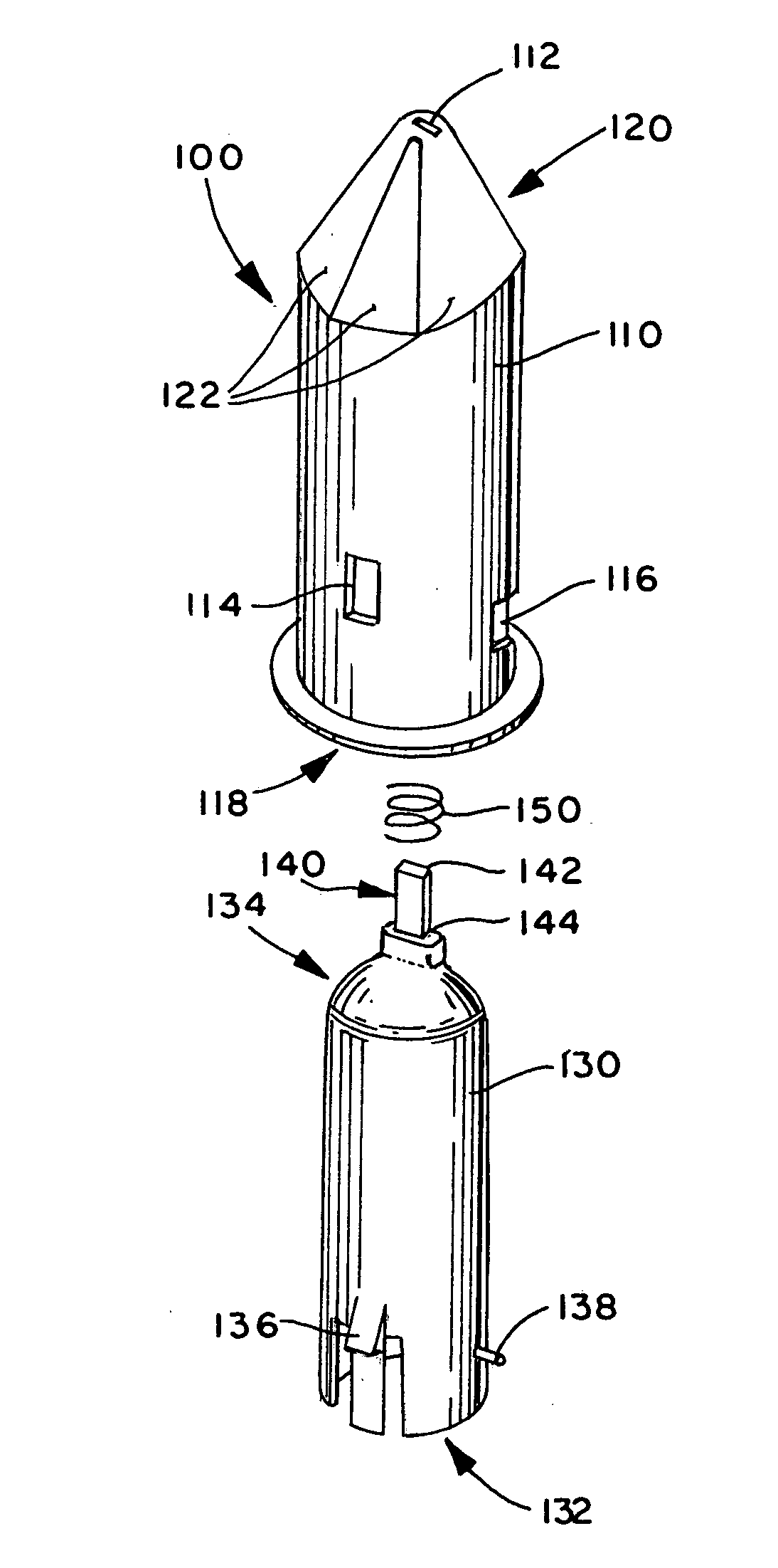
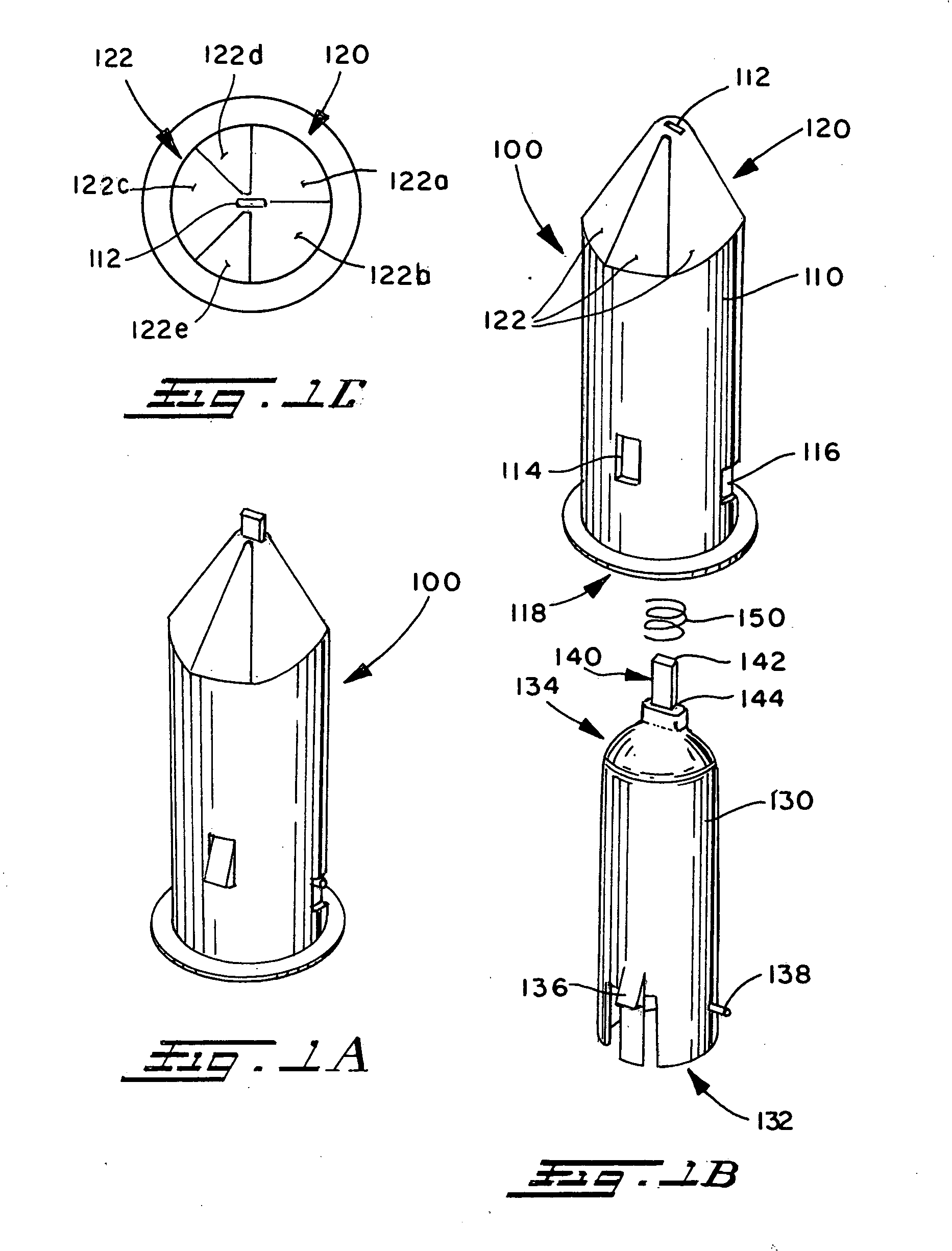
[0019] With reference to FIGS. 1A-1C, a first embodiment 100 of a cutter device is shown. In particular, FIG. 1A illustrates a perspective view of the cutter device 100 in its assembled configuration. Generally, the cutter device 100 comprises an outer sleeve 110, an inner sleeve 130, a blade 140 and a biasing element 150. The outer sleeve 110 includes a slot 112, a button aperture 114, at least one retaining rib aperture 116, an open end 118 and a closed end 120. The closed end 120 further comprises a plurality of flat guide surfaces 122.

[0020] The inner sleeve 130 generally includes an open end 132, a closed end 134, a button 136 and at least one retaining rib 138. The blade 140 is disposed on the closed end 134 of the inner sleeve 130. The blade 140 includes a sharp end 142 and a shank end 144. The sharp end 142 is intended to serve as the cutting edge for the cutter device 100. The shank end 144 provides a surface by which to attach the blade 140 to the inner sleeve 130. The bu...


PUM

PropertyMeasurementUnit
angleaaaaaaaaaa
90° angleaaaaaaaaaa
intersection angleaaaaaaaaaa

Abstract

The present invention involves a hand-held cutter device that is adapted to be held by a human hand, over a human finger, or between the human fingers. The cutter device includes a generally cylindrical inner sleeve slideably engaged with a generally cylindrical outer sleeve, where each sleeve includes an open end and a closed end. The inner sleeve has an extended position and a retracted position. A blade for cutting various materials is attached to the closed of the inner sleeve. A biasing element is confined between the sleeves and urges the inner sleeve into the retracted position. The closed end of the outer sleeve may include a plurality of flat guide surfaces, at least one straight guide groove, and or at least one guide rib. At least two of the plurality of flat guide surfaces may intersect at about a 90 degree angle and the at least one straight guide groove may be located within any of the plurality of flat guide surfaces.

Description

BACKGROUND [0001] The present invention relates to cutting devices for cutting various types of material such as thin vinyl, plastic, paper, cardboard, or string. In particular, the present invention is directed to the art of hand-held cutting devices and cutting devices capable of being supported by at least one human finger. [0002] Generally, finger mounted cutting devices exist in the art. However, these devices have a number of limitations. One limitation involves the breadth of material that prior art cutters can cut. In most cases, the prior art cutters are capable of cutting only a limited range of materials (e.g. grape stems or envelopes). Another limitation involves the ergonomic and safety aspects of the prior art cutters. Many prior art devices use an exposed fixed blade design which can lead to severe cuts if the user is not extremely careful at all times. In addition, other prior art devices attach to the user's hand in a manner that may result in fatigue and discomfort...

Claims


Application Information

Patent Timeline
Patent Type & Authority Applications(United States)
IPC IPC(8): B26B27/00
CPCB26B27/007Y10T83/0237Y10T83/8785Y10T83/9423
Inventor WILLIAMS, IRENE E.
Owner SHURTECH BRANDS
Why Eureka
Try Eureka