Interference randomization of control channel elements
What is AI technical title?
AI technical title is built by Patsnap AI team. It summarizes the technical point description of the patent document.
a control channel and randomization technology, applied in the field of telecommunication system methods and arrangement, can solve the problems of interference, potential overlap of transmissions from different cells in time or frequency, interference with each other, etc., and achieve the effect of improving the mapping or placing of the used symbol group, improving performance, and flexibility with resp
Active Publication Date: 2018-05-01
TELEFON AB LM ERICSSON (PUBL)
View PDF8 Cites 0 Cited by
Summary
Abstract
Description
Claims
Application Information
AI Technical Summary
This helps you quickly interpret patents by identifying the three key elements:
Problems solved by technology
Method used
Benefits of technology
Benefits of technology
[0019]flexibility in that it can handle a different frequency bandwidth in the control channel transmission resources, a different number of OFDM symbols in the control channel transmission resources, and a different number of symbol groups in the information stream;
[0022]A solution according to the present disclosure for accomplishing the above objectives is to use a flexible symbol group interleave that can handle control channel parameters that may not be fixed in time or in the cellular system. These parameters include: the number of OFDM sub-carriers in the control channel transmission resources; the number of OFDM symbols in the control channel transmission resources; the number of symbol groups in the control channel signal; and the number of available symbols groups in the control channel transmission resources for placing the control channel symbol groups. Combined with an optional cell-specific cyclic shift, this allows for interference randomization. Further, by regrouping symbol groups by resource block order in the control channel transmission resources and designing the symbol group permutation pattern taking the resource block size into account, frequency diversity can be provided. An additional aspect of this approach is that interference can be further reduced by advantageously locating the control channel symbol groups within the available OFDM symbols in the control channel transmission resources in case there is a greater number of potential symbol groups available in the control channel transmission resources than are required within the control channel information stream.
[0026]The described aspects and embodiments of the present disclosure provide the advantage of renumbering of the symbol groups so that frequency diversity can easily be accounted for in the interleave design.
[0028]Yet another advantage is enhanced performance due to better mapping or placing of the used symbol groups from a larger subset of symbols groups.
[0029]A further advantage is flexibility with respect to the frequency bandwidth, number of OFDM symbols, and number of information symbol groups used for control channel signaling.
Problems solved by technology
The transmissions from different cells potentially overlap in either time or frequency and may interfere with each other.
This affects the level of interference that affects a mobile and it may create an uneven distribution of interference to different mobiles.
If certain control channel elements from one base station is transmitted with high power, they might cause disturbance to corresponding control channel elements transmitted from another base station.
While randomization of the interfering CCE groups reduces interference consistently, a truly random symbol permutation is not practical due to the required signaling aspects between the base station and the mobile for such a scheme.
Method used
Image
Click on the blue label to locate the original text in one second.
Reading with bidirectional positioning of images and text.
Examples
Embodiment Construction
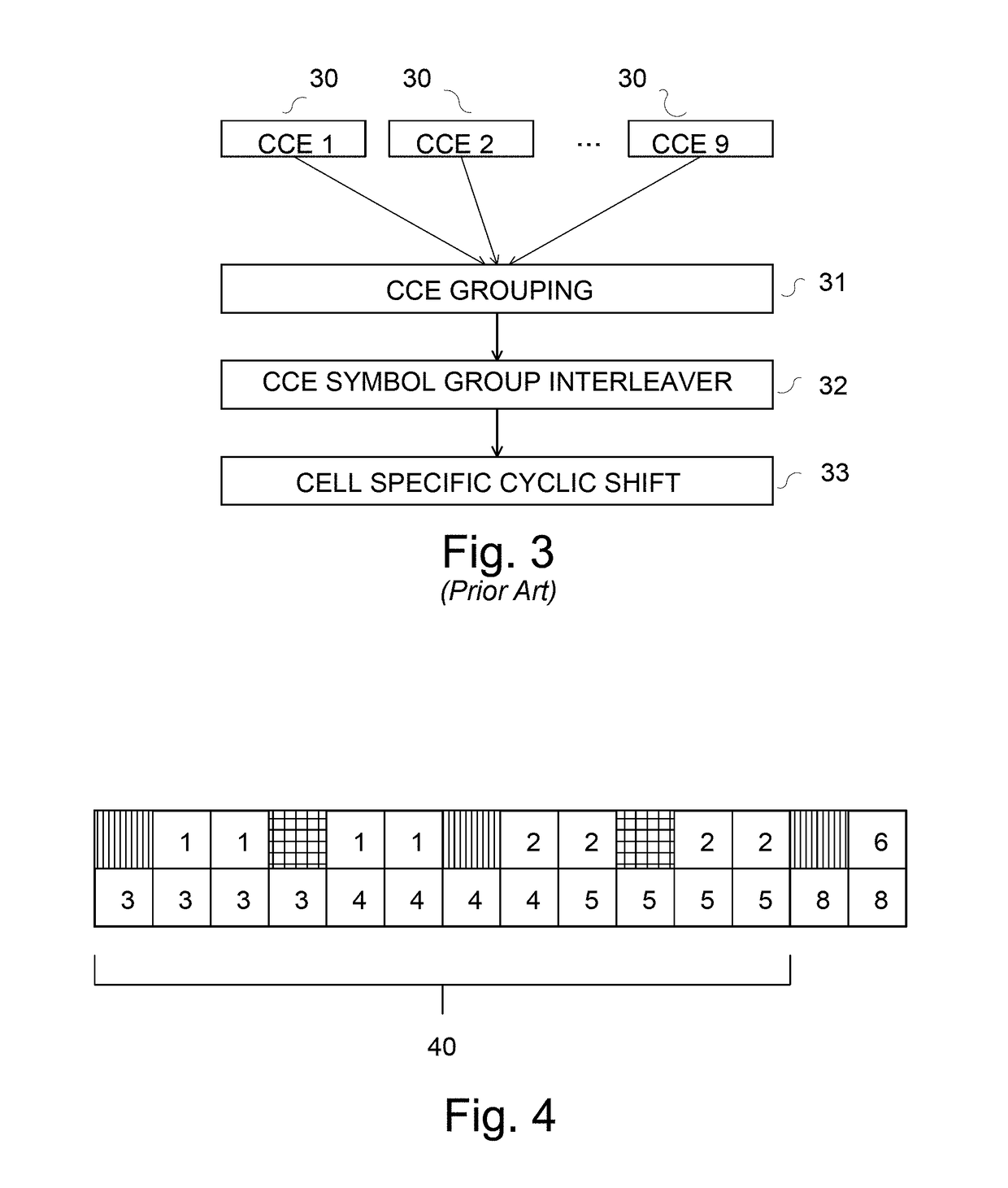
[0046]In the following, various embodiments of the present disclosure will be described. The approach described below is intended for flexibility with performance approaching that of the random interleaving approach described above. Considering the 72 symbol group example discussed above, where the cell-specific cyclic shift is intended to randomize interference between cells. However, when changing CCE or CCE group sizes, or bandwidth or OFDM symbol allocations in the control channel transmission resources, it becomes difficult to design an interleaving pattern to handle this variability. Consider the case of having 72 symbol groups within a CCE transmitted within a 5 MHz bandwidth. There are only 48 sub-carriers available in the first OFDM symbol, therefore either two or three OFDM symbols must be used to transmit the entire CCE. FIG. 4 shows the two-symbol structure with resource block 40 while FIG. 5 shows the three symbol structure of the control channel transmission resources ...
PUM
Abstract
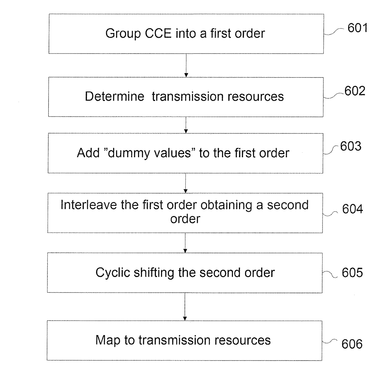
A method and a radio base station for interleaving control channel data to be transmitted in a telecommunications system are described. The method comprises grouping the control channel elements CCE1-CCEn into a first order of control channel symbol groups, adding symbol groups comprising dummy values or zeros to the first order of control channel symbol groups based on a number of available symbol group positions for the shared control channel, interleaving the first order of the control channel symbol groups resulting in an a second order, and mapping the second order of control channel symbol groups to the available control channel transmission resources.
Description
RELATED APPLICATIONS[0001]This application is a continuation of U.S. application Ser. No. 14 / 734,518, which was filed on Jun. 9, 2015, which is a continuation of U.S. application Ser. No. 13 / 856,506, now U.S. Pat. No. 9,084,253, which was filed on Apr. 4, 2013, which claims the benefit of U.S. application Ser. No. 12 / 679,419, now U.S. Pat. No. 8,428,164, which was filed on Mar. 22, 2010, which was the National Stage of International Application No. PCT / SE2008 / 050372, filed Mar. 31, 2008, which claims the benefit of U.S. Provisional Application 60 / 974,949, filed Sep. 25, 2007, the disclosures of each of which are incorporated herein by reference in their entirety.TECHNICAL FIELD[0002]The present disclosure relates to a method and arrangement in a telecommunication system, in particular it relates to a method and arrangement for symbol group interleaving in a telecommunication system. The present disclosure also relates to a method for mapping symbol groups to be interleaved in a tele...
Claims
Application Information
Patent Timeline
Application Date:The date an application was filed.
Publication Date:The date a patent or application was officially published.
First Publication Date:The earliest publication date of a patent with the same application number.
Issue Date:Publication date of the patent grant document.
PCT Entry Date:The Entry date of PCT National Phase.
Estimated Expiry Date:The statutory expiry date of a patent right according to the Patent Law, and it is the longest term of protection that the patent right can achieve without the termination of the patent right due to other reasons(Term extension factor has been taken into account ).
Invalid Date:Actual expiry date is based on effective date or publication date of legal transaction data of invalid patent.

