Communications terminal and method

a technology applied in the field of communication terminal and communication method, can solve problems such as non-delay-tolerant data packet transmission, and achieve the effect of improving both power conservation and efficiency

Active Publication Date: 2018-05-15
INTERDIGITAL PATENT HLDG INC
View PDF20 Cites 3 Cited by
  • Summary
  • Abstract
  • Description
  • Claims
  • Application Information

AI Technical Summary

Benefits of technology

[0008]Embodiments of the present technique can provide an arrangement in which data packets which can be classified into at least delay tolerant and non-delay tolerant data packets are transmitted by a communications terminal in a way which can conserve the power of the communications terminal and more efficiently utilise the communications resources of a wireless access interface provided by a mobile communications network. As will be appreciated delay tolerant data packets can be delayed for a predetermined time or indefinitely and so therefore buffered in an input buffer before being transmitted. Depending on currently experienced radio conditions for transmitting the data packets a communications terminal can buffer the input packets data packets for delay tolerant data packets until the channel is in a state in which communications resources can be used efficiently to transmit the data packets. Furthermore, signalling and control data is required to be transmitted from both the communications terminal and the mobile communications network before a communications terminal can access communications resources for transmitting the data packets. Therefore the more data packets which can be transmitted in any connection session, such as when a communications terminal has established a bearer via the wireless access interface the more efficient the transmission of the data packets. Thus by queuing the data packets in an input buffer until a predetermined number of the delay tolerant data packets are received, a more efficient use of radio communications resources can be achieved. However communications terminals also need to transmit the non-delay tolerant data packets. If one or more of the non-delay tolerant data packets are present in the input buffer then depending on the state of the radio communications channel, the communications terminal can transmit the non-delay tolerant data packets with the delay tolerant data packets in order to achieve both an efficiency gain in the use of the radio communications resources and conserving an amount of power available to the mobile communications terminal. The power conservation is achieved in one example by only transmitting the data packets when the state for radio communications exceeds a predetermined quality metric. Thus the communications terminal only transmits data packets as a function of the state of the radio communications channel and the number of delay tolerant and non-delay tolerant data packets present in an input buffer. Accordingly, with this combination of features, a communications terminal is both able to conserve power and utilise resources of the communications wireless access interface more efficiently.
[0010]As will be appreciated various combinations of states for radio communications and numbers of data packets present in an input buffer can be combined in order to achieve an improvement in both power conservation for the communications terminal and an efficiency with which communications resources are used.

Problems solved by technology

However communications terminals also need to transmit the non-delay tolerant data packets.

Method used


Image

  • Communications terminal and method
  • Communications terminal and method
  • Communications terminal and method

Examples


example network

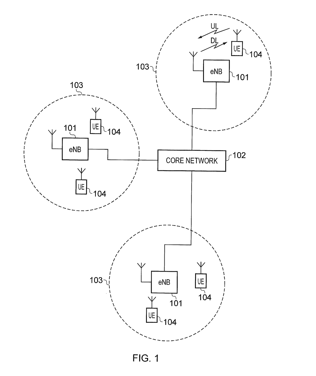
[0028]FIG. 1 provides a schematic diagram illustrating the basic functionality of a conventional mobile communications system. In FIG. 1, a mobile communications network includes a plurality of base stations 101 connected to a core network 102. Each base station provides a coverage area 103 (i.e. a cell) within which data can be communicated to and from communications terminals 104. Data is transmitted from a base station 101 to a communications terminal 104 within a coverage area 103 via a radio downlink. The data is transmitted from a communications terminal 104 to a base station 101 via a radio uplink. The core network 102 routes the data to and from the base stations 104 and provides functions such as authentication, mobility management, charging and so on. The base stations 101 provide a wireless access interface comprising the radio uplink and the radio downlink for the communications terminals and form examples of infrastructure equipment or network elements for the mobile co...

example architecture

[0098]FIG. 12 provides a schematic diagram showing part of an adapted LTE mobile telecommunication system arranged in accordance with an example of the present disclosure. The system includes an adapted enhanced Node B (eNB) 1001 connected to a core network 1008 which communicates data to a plurality of conventional LTE terminals 1003, 1007 and reduced capability communications terminals 1002 within a coverage area (i.e. cell) 1004. Each of the reduced capability terminals 1002 has a transceiver unit 1005 which includes a receiver unit capable of receiving signals via a wireless access interface provided by the eNodeB 1001 and a transmitter unit capable of transmitting signals via the wireless access interface.

[0099]In one example embodiment the example reduced capability terminals 1002 include a processor 1708 and a controller 1704 which are adapted to perform the process steps referred to above with reference to FIGS. 7 to 11. Thus, in this example configuration architecture the c...


PUM


Abstract

A communications terminal includes a transmitter to transmit signals, a receiver to receive signals, and a controller to control the transmitter and receiver. The controller includes an input buffer receiving data packets for transmission. The controller can identify whether the received data packets are delay tolerant or non-delay tolerant, to determine a current state for communications for transmitting the data packets and based on predetermined conditions including a current state for radio communications, an amount of the delay tolerant data packets in the input buffer, and an amount of the non-delay tolerant packets in the input buffer, either transmit the non-delay tolerant data packets or transmit the non-delay tolerant data packets and the delay tolerant data packets from the input buffer to a mobile communications network using the transmitter, or maintain the delay tolerant or non-delay tolerant data packets in the input buffer until the predetermined conditions are satisfied.

Description

CROSS-REFERENCE TO RELATED APPLICATIONS[0001]The present application is based on PCT filing PCT / GB2014 / 052000 filed Jul. 2, 2014, and claims priority to European Patent Application 13 179 483.6, filed in the European Patent Office on Aug. 6, 2013, the entire contents of each of which being incorporated herein by reference.TECHNICAL FIELD OF THE DISCLOSURE[0002]The present disclosure relates to communications terminals and methods for communicating and wireless communications networks and methods of communicating via wireless communications networks.BACKGROUND OF THE DISCLOSURE[0003]Third and fourth generation mobile telecommunication systems, such as those based on the 3GPP defined UMTS and Long Term Evolution (LTE) architecture are able to support more sophisticated services than simple voice and messaging services offered by previous generations of mobile telecommunication systems.[0004]For example, with the improved radio interface and enhanced data rates provided by LTE systems,...

Claims


Application Information

Patent Timeline
Patent Type & Authority Patents(United States)
IPC IPC(8): H04L12/851H04L12/801H04L12/835H04L12/911H04W36/02H04W52/02H04L12/853H04W28/02H04L47/2416H04L47/30H04L47/32
CPCH04L47/24H04L47/2416H04L47/29H04L47/30H04L47/741H04W28/0231H04W36/023H04W52/0222Y02D70/00Y02D70/1242Y02D70/1262Y02D70/21Y02D70/23Y02D30/70
Inventor WAKABAYASHI, HIDEJIWEBB, MATTHEW WILLIAM
Owner INTERDIGITAL PATENT HLDG INC
Why Eureka
Try Eureka