Supercharge Your Innovation With Domain-Expert AI Agents!

Light-emitting device and luminaire

a technology of light-emitting devices and luminaires, which is applied in the direction of semiconductor devices for light sources, fixed installations, lighting and heating apparatus, etc., can solve the problems of larger size and cost of luminaires disclosed in ptl 1 and achieve the effect of reducing the number of light-emitting elements

Inactive Publication Date: 2018-05-15
PANASONIC INTELLECTUAL PROPERTY MANAGEMENT CO LTD
View PDF28 Cites 1 Cited by
  • Summary
  • Abstract
  • Description
  • Claims
  • Application Information

AI Technical Summary

Benefits of technology

The present disclosure aims to offer a light-emitting device and a luminaire that can perform color toning while reducing the number of light-emitting elements required. This helps in optimizing the use of resources and minimizing the size of the device or lamp.

Problems solved by technology

This causes the luminaire disclosed in PTL 1 to be larger in size and cost than the luminaire with no dimming function.

Method used


Image

  • Light-emitting device and luminaire
  • Light-emitting device and luminaire
  • Light-emitting device and luminaire

Examples


embodiment 1

[0027]Hereinafter, a light-emitting device and a luminaire including the light-emitting device according to Embodiment 1 will be described.

[1-1. Luminaire Configuration]

[0028]First, the configuration of the luminaire according to the present embodiment will be described with reference to the drawings.

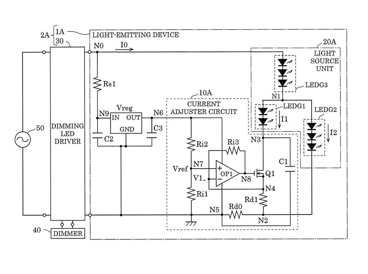
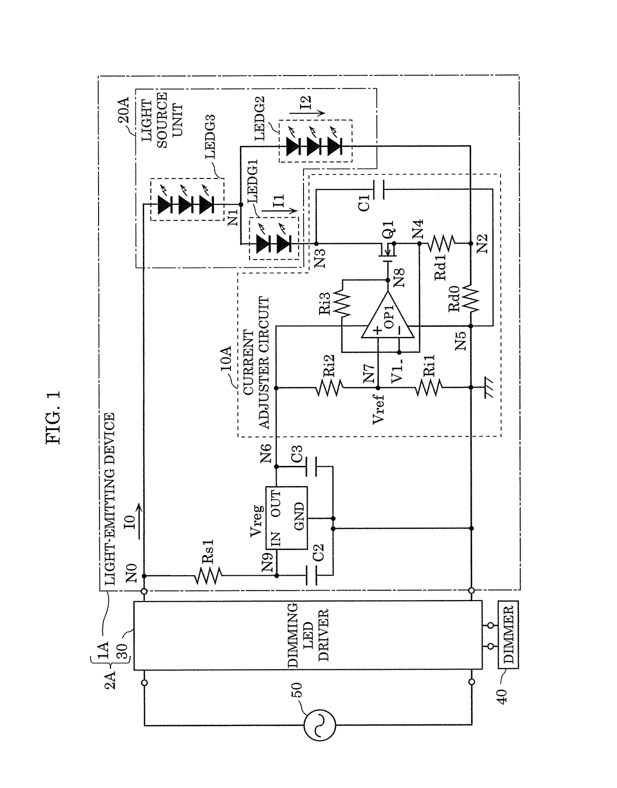
[0029]FIG. 1 is a circuit diagram illustrating an example of the circuit configuration of luminaire 2A according to the present embodiment.

[0030]Luminaire 2A has dimming and color toning functions and includes dimming LED driver 30 and light-emitting device 1A as illustrated in FIG. 1. Luminaire 2A is supplied with AC power from AC power supply 50. The dimming level of luminaire 2A is determined by dimmer 40.

[0031]AC power supply 50 is, for example, a grid power supply such as an external, commercial power supply.

[0032]Dimmer 40 is a device which sets a dimming level of the luminaire. In the present embodiment, dimmer 40 outputs a dimming signal indicating a dimming level to dimming LED...

embodiment 2

[0122]Hereinafter, a light-emitting device and a luminaire including the light-emitting device according to Embodiment 2 will be described.

[0123]While Embodiment 1 has described light-emitting device 1A which can continuously change the color temperature, the present embodiment will describe a light-emitting device and a luminaire which can discretely change the color temperature. Hereinafter, the light-emitting device and the luminaire according to the present embodiment will be described, focusing on differences from light-emitting device 1A and luminaire 2A according to Embodiment 1.

[2-1. Luminaire Configuration]

[0124]Hereinafter, the configurations of the light-emitting device and the luminaire including the light-emitting device according to the present embodiment will be described with reference to the drawings.

[0125]FIG. 7 is a circuit diagram illustrating an example of the circuit configuration of luminaire 2B according to the present embodiment.

[0126]Luminaire 2B has dimmin...

embodiment 3

[0147]Hereinafter, a light-emitting device and a luminaire including the light-emitting device according to Embodiment 3 will be described.

[0148]While Embodiment 2 has described light-emitting device 1B which changes the color temperature using two switching elements, the present embodiment will describe a light-emitting device and a luminaire which can change the color temperature using one switching element. Hereinafter, the light-emitting device and the luminaire according to the present embodiment will be described, focusing on differences from light-emitting device 1B and luminaire 2B according to Embodiment 2.

[3-1. Luminaire Configuration]

[0149]Hereinafter, the configurations of the light-emitting device and the luminaire according to the present embodiment will be described with reference to the drawings.

[0150]FIG. 9 is a circuit diagram illustrating an example of the circuit configuration of luminaire 2C according to the present embodiment.

[0151]As illustrated in FIG. 9, lum...


PUM


Abstract

A light-emitting device includes: a first light-emitting element array including one of a single first light-emitting element or a plurality of first light-emitting elements connected in series, and having a first emission color; a second light-emitting element array including one of a single second light-emitting element or a plurality of second light-emitting elements connected in series, and having a second emission color different from the first emission color, the second light-emitting element array being connected to the first light-emitting element array in parallel; and a third light-emitting element array including one of a single third light-emitting element or a plurality of third light-emitting elements connected in series, and having a third emission color different from the first emission color and the second emission color, the third light-emitting element array being connected to the first light-emitting element array and the second light-emitting element array in series.

Description

CROSS REFERENCE TO RELATED APPLICATION[0001]This application claims the benefit of priority of Japanese Patent Application Number 2015-241593 filed on Dec. 10, 2015, the entire content of which is hereby incorporated by reference.BACKGROUND[0002]1. Technical Field[0003]The present disclosure relates to a light-emitting device including a plurality of light-emitting element arrays which are different from one another in emission color, and a luminaire using the light-emitting device.[0004]2. Description of the Related Art[0005]Conventionally, luminaires which can change color temperature, that is, luminaires which can perform color toning are known (for example, see Patent Literature 1 (PTL 1): Japanese Unexamined Patent Application Publication No. 2015-56381).[0006]A light source of the luminaire disclosed in PTL 1 includes a first light-emitting unit having a plurality of first light-emitting elements and a second light-emitting unit having a plurality of second light-emitting elem...

Claims


Application Information

Patent Timeline
Patent Type & Authority Patents(United States)
IPC IPC(8): H05B37/02H05B33/08F21V23/00F21S8/02H05B44/00F21Y115/10
CPCH05B33/0866H05B33/0827F21Y2115/10F21V23/009F21S8/02H05B45/24H05B45/375H05B45/3725H05B45/38H05B45/46
Inventor SEKI, KEISUKE
Owner PANASONIC INTELLECTUAL PROPERTY MANAGEMENT CO LTD
Features
  • R&D
  • Intellectual Property
  • Life Sciences
  • Materials
  • Tech Scout
  • Unparalleled Data Quality
  • Higher Quality Content
  • 60% Fewer Hallucinations
Learn More