Steerable antenna assembly utilizing a dielectric lens

a dielectric lens and antenna technology, applied in the field of antennas, can solve the problems of limiting the range, maneuverability and overall functionality of the uav, limiting the application space of the uav system, and the ability of the ut antenna to efficiently track the aerial vehicle in flight,

Active Publication Date: 2018-05-22
THE BOEING CO
View PDF5 Cites 9 Cited by
  • Summary
  • Abstract
  • Description
  • Claims
  • Application Information

AI Technical Summary

Problems solved by technology

The control and data performance of this wireless link significantly limits the range, maneuverability and overall functionality of the UAV.
As UAV use has expanded, the wireless link capabilities have become a limiting factor in the UAV system application space.
The UT antenna's ability to efficiently track the aerial vehicle in flight is a significant coverage and range limitation.
The costs, complexity and logistics of multi-site terrestrial systems has limited their application.
Satellite system complexity and data latency makes real-time control and observation of UAVs extremely complex and expensive.
Mechanically articulated antennas have significant response time and pointing accuracy issues tracking the aerial vehicle.
Phased array antennas are complex to setup and operate, consume large amounts of power, and are expensive so their practical application is limited to high-end systems.

Method used


Image

  • Steerable antenna assembly utilizing a dielectric lens
  • Steerable antenna assembly utilizing a dielectric lens
  • Steerable antenna assembly utilizing a dielectric lens

Examples


Embodiment Construction

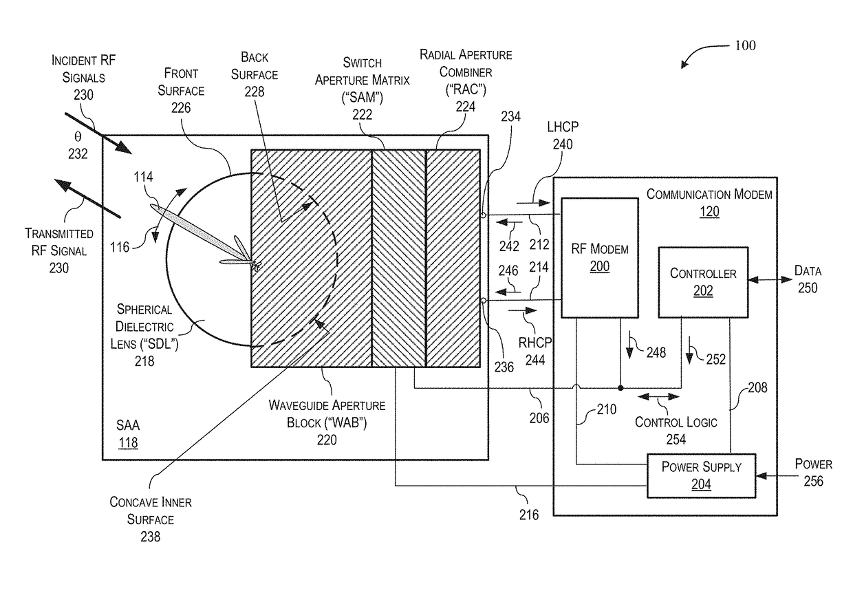
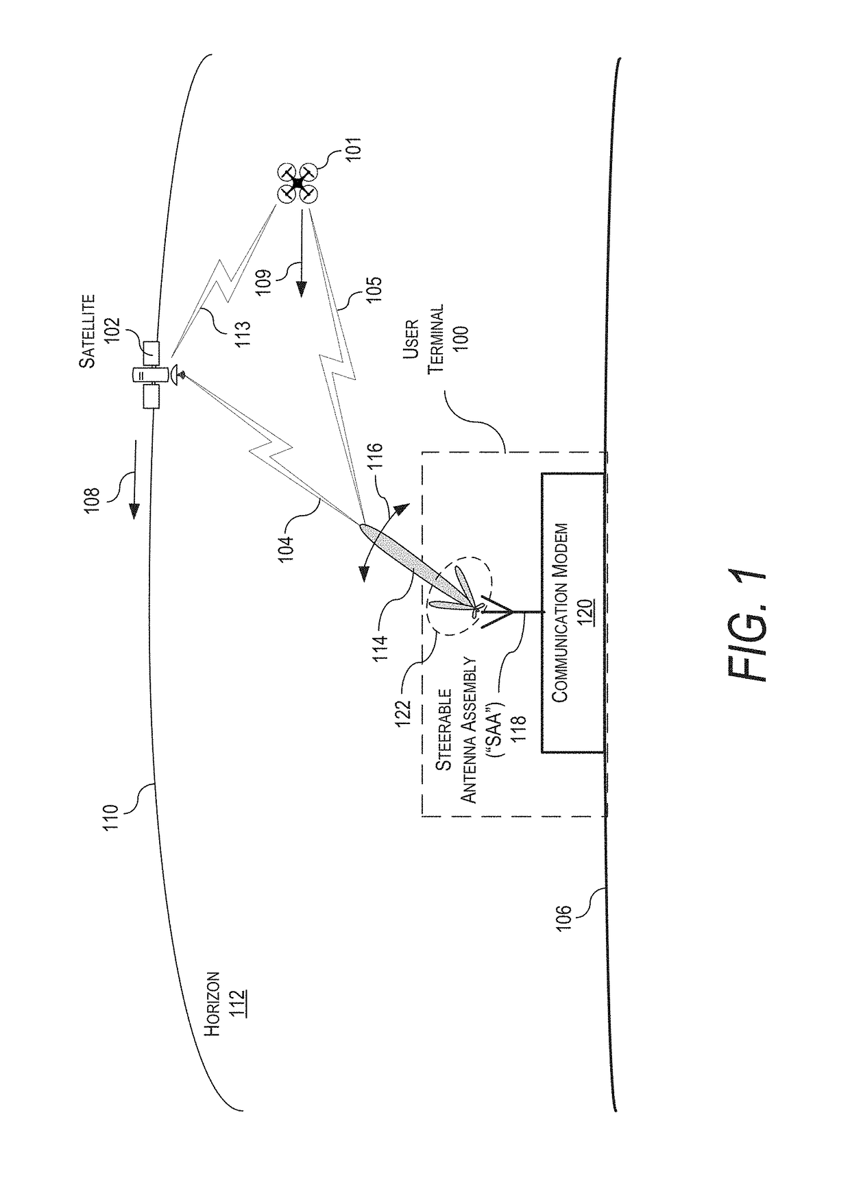
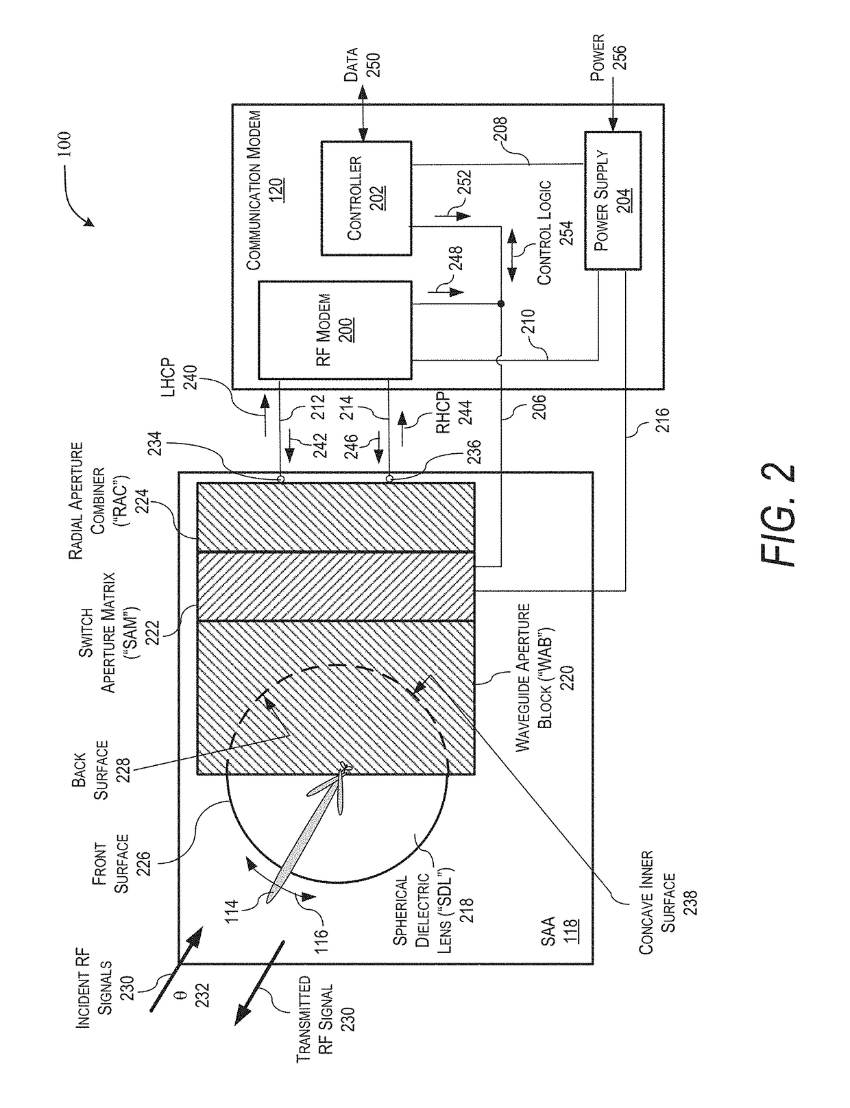
[0029]A steerable antenna assembly (“SAA”) for receiving a plurality of incident radio frequency (“RF”) signals at a plurality of incident angles is disclosure. The SAA includes an approximately spherical dielectric lens (“SDL”), a waveguide aperture block (“WAB”), a switch aperture matrix (“SAM”), and a radial aperture combiner (“RAC”). The SDL includes a front surface and a back surface, where the SDL is configured to receive and focus the plurality of incident RF signals to create a plurality of focused RF signals at a plurality of focal points approximately along the back surface of the SDL. The plurality of focal points have positions along the back surface of the SDL that correspond to the plurality of incident angles of the plurality of incident RF signals. The WAB is positioned adjacent to the back surface of the SDL, where the WAB is in signal communication with the back surface of the SDL and the WAB is configured to receive the plurality of focused RF signals. The SAM in ...


PUM


Abstract

A steerable antenna assembly (“SAA”) for receiving a plurality of incident radio frequency (“RF”) signals at a plurality of incident angles is disclosure. The SAA includes an approximately spherical dielectric lens (“SDL”), a waveguide aperture block (“WAB”), a switch aperture matrix (“SAM”), and a radial aperture combiner (“RAC”). The SDL receives and focuses the plurality of incident RF signals creating a plurality of focused RF signals at a plurality of focal points approximately along the back surface of the SDL. The WAB is positioned adjacent to the back surface of the SDL and receives the plurality of focused RF signals. The SAM electronically steers a beam of a radiation pattern produced by the SAA and switch between the pluralities of focused RF signals based on electronically steering the beam. The RAC produces a received RF signal from the plurality of focused RF signals.

Description

CROSS-REFERENCE TO RELATED APPLICATION AND CLAIM OF PRIORITY[0001]The present patent application is a utility application, claiming priority under 35 U.S.C. § 119(e) to U.S. Provisional Application No. 62 / 379,031, filed on Aug. 24, 2016, titled “User Terminal Including Dielectric Lens With Waveguide Assembly and Method of Using,” to Savage et al., which is hereby incorporated by reference in its entirety.BACKGROUND[0002]1. Field[0003]The present disclosure relates generally to antennas and, more particularly, to an antenna system utilizing a spherical lens and an antenna array to electronically scan the antenna system.[0004]2. Related Art[0005]The use of unmanned aerial vehicles (“UAVs”), commonly referred to as drones, has experienced explosive growth in this decade. Most UAVs utilize wireless technologies to control and communicate data between the UAV and a user terminal (“UT”). The control and data performance of this wireless link significantly limits the range, maneuverability...

Claims


Application Information

Patent Timeline
Patent Type & Authority Patents(United States)
IPC IPC(8): H04B7/00H01Q1/24H04B7/08H01Q13/06H01Q1/28H01Q3/34
CPCH04B7/0874H01Q1/241H01Q13/06H01Q3/34H01Q1/28H01Q19/06H01P5/12H01Q15/08H01Q19/062
Inventor SAVAGE, LARRY L.THACKER, COREY M.
Owner THE BOEING CO
Why Eureka
Try Eureka