
Electrical modules and modular electronic building systems

a technology of electronic building system and electrical modules, applied in the field of electrical components, can solve the problems of not knowing how these devices work, or how to make their own, and the gap between what is taught to an average person and what is used and consumed by that person, and cannot be expanded in any other direction

Inactive Publication Date: 2018-05-22
MICRODUINO INC +1
View PDF4 Cites 11 Cited by
  • Summary
  • Abstract
  • Description
  • Claims
  • Application Information

AI Technical Summary

Benefits of technology

This patent describes a modular electrical building system that includes at least two electrical modules. Each module has a housing with N pin portions, N conduction members, and N magnetic members. The N pin portions are plates with a through-hole towards their thickness direction, connected to one conduction member and one magnetic member. The conduction members have two parts: a first part on the surface of the housing and a second part on the inner wall of the through-hole. The magnetic members are designed to fit into the through-hole of the pin portions and establish magnetic connection with the corresponding magnetic member of another module, allowing the modules to contact and rotate against each other. The magnetic members are also electrically conductive, enabling electrical connection between the modules. The technical effects of this invention are an efficient and flexible way to connect electrical components in a modular system.

Problems solved by technology

However, most of them don't know how these devices work, or how to make their own.
In fact, there is a big gap between what is taught to an average person and what is used and consumed by that person.
However, they cannot be expanded in any other direction(s), and the connection angles between the electrical modules cannot be adjusted.

Method used


Image

  • Electrical modules and modular electronic building systems
  • Electrical modules and modular electronic building systems
  • Electrical modules and modular electronic building systems

Examples


Embodiment Construction

[0045]Reference will now be made in detail to exemplary embodiments of the disclosure, which are illustrated in the accompanying drawings. Wherever possible, the same reference numbers will be used throughout the drawings to refer to the same or like parts.

[0046]The present disclosure provides an electrical module (also referred to as a “module” or “electrical block” or “block”), and a modular electronic building system including a plurality of (electrical) modules stacked together.

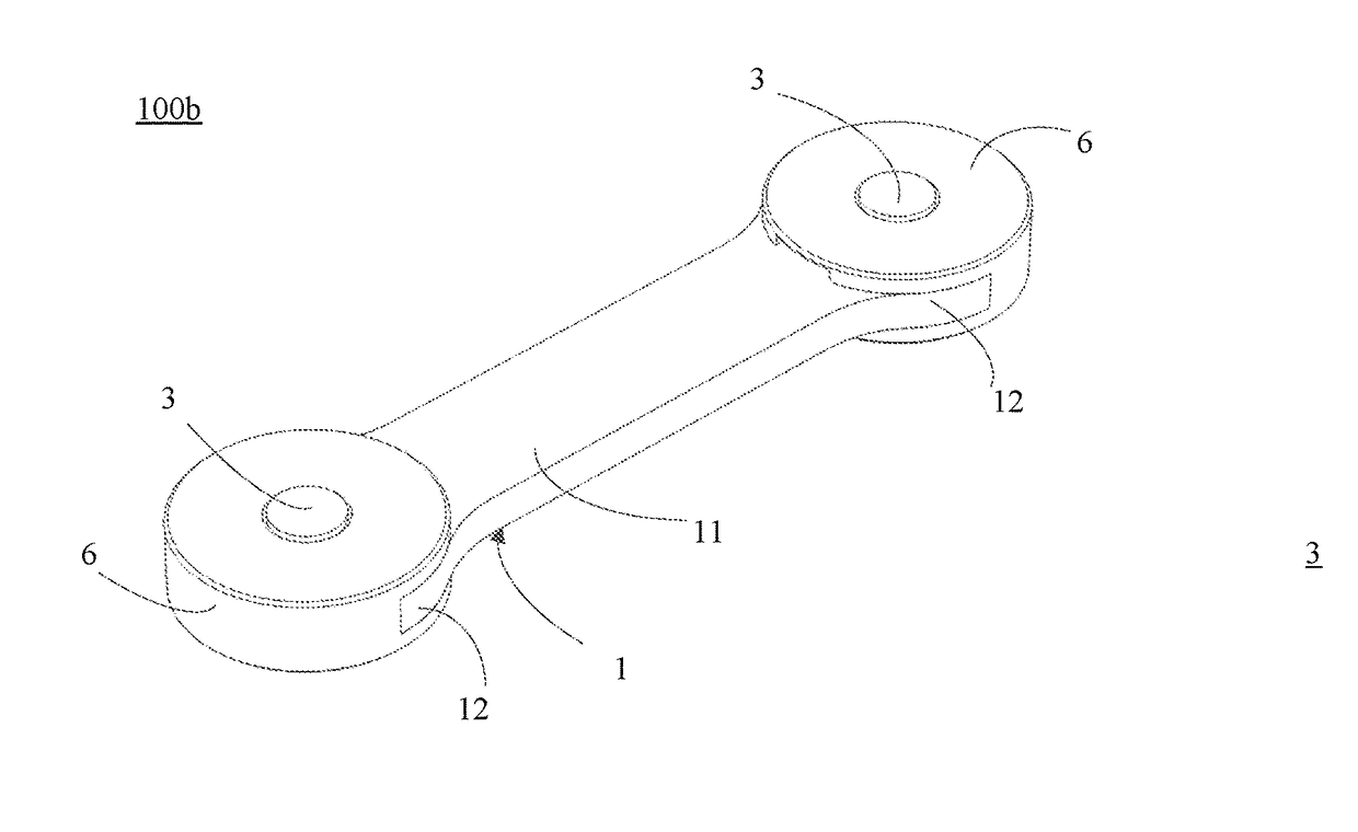
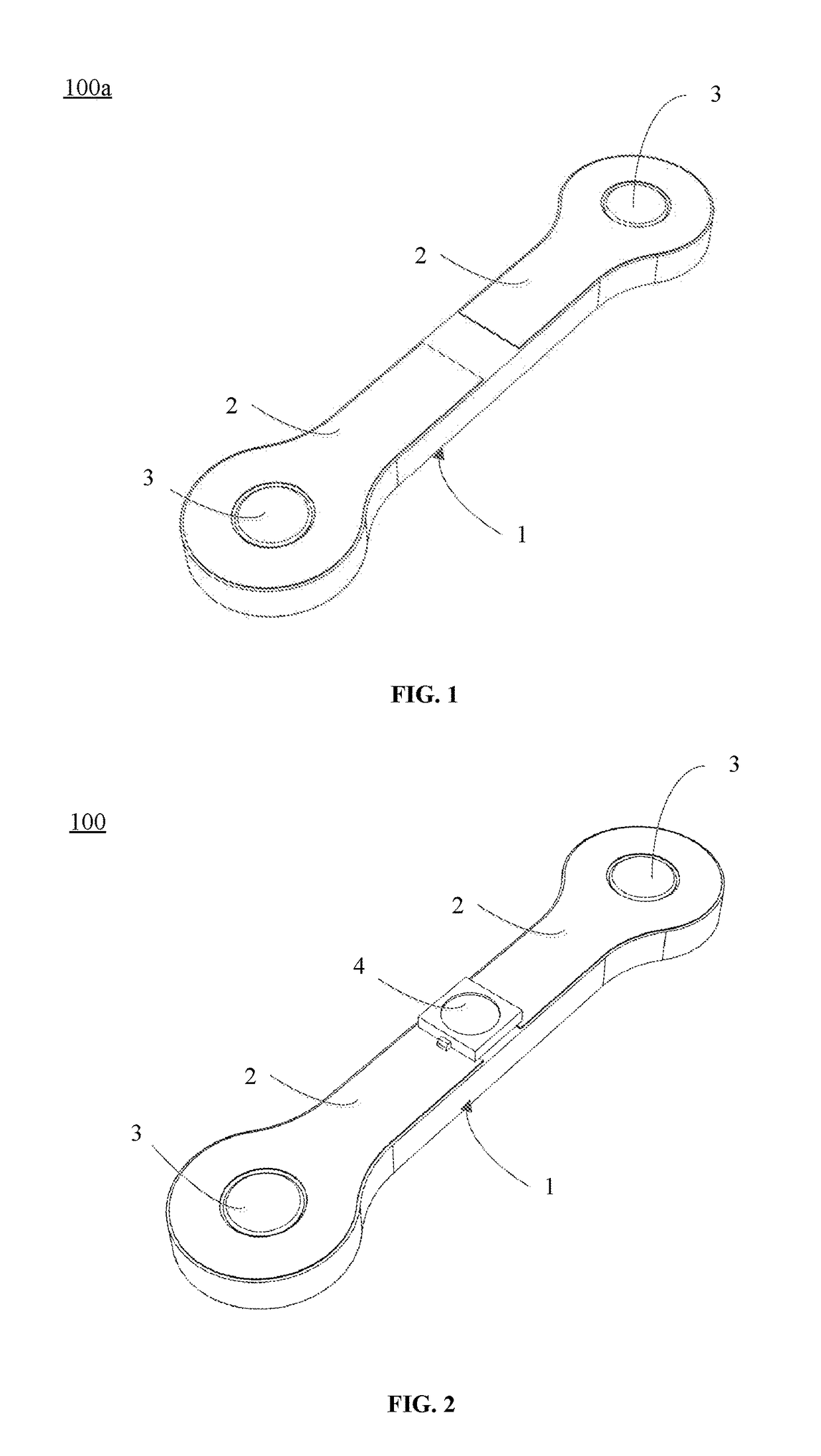
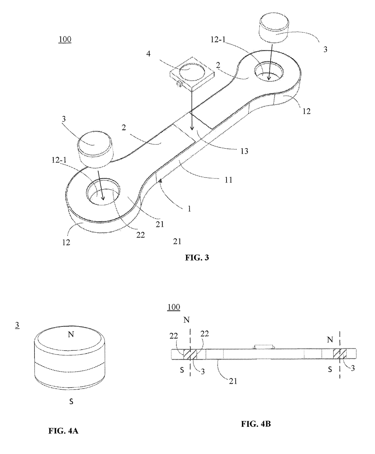
[0047]FIGS. 1-3 illustrate an exemplary bone-like module used to build a modular electronic building system consistent with various disclosed embodiments. As shown, the exemplary bone-like module 100 may include at least a base module 100a including a housing member 1, conduction members 2, and magnetic members 3. The exemplary module 100 may further include an electrical component 4. In some embodiments, the disclosed module may only include the base module 100a. In some embodiments, the disclosed electr...


PUM


Abstract

The present disclosure provides an electrical module and a modular building system including electrical modules. The electrical module includes a housing member including N pin portions and a connecting portion that connects the N pin portions, where N is greater than 1; N conduction members unconnected with each other; and N magnetic members. Each pin portion is a plate having a through-hole towards its thickness direction, and corresponds to one conduction member and one magnetic member. Each conduction member includes: a first part electrically connected with a lead of an electrical component; and a second part electrically connected with the corresponding magnetic member. Each magnetic member fills the through-hole of the corresponding pin portion, and establishes magnetic connection with a magnetic member of another electrical module in thickness direction to allow the two electrical modules to contact and rotate against each other using a contacting point as a rotation pivot.

Description

CROSS-REFERENCES TO RELATED APPLICATIONS[0001]This application claims priority to Chinese Patent Application No. CN 201510815186.0, filed on Nov. 25, 2015, the entire content of which is incorporated herein by reference.FIELD OF THE DISCLOSURE[0002]The present disclosure generally relates to the field of electronics and, more particularly, relates to electrical modules, modular electronic building systems, and electrical building products.BACKGROUND[0003]Nowadays, technological devices are widely used by children and / or adults in their day-to-day life. However, most of them don't know how these devices work, or how to make their own. In fact, there is a big gap between what is taught to an average person and what is used and consumed by that person. It is therefore desirable for children or adults to be able to use functional electrical modules without having to be an expert to program or learn the many complexities involved with these advanced electronics. It is also desirable for ...

Claims


Application Information

Patent Timeline
Patent Type & Authority Patents(United States)
IPC IPC(8): H05K7/02A63H33/04A63H33/26
CPCH05K7/023A63H33/042H05K7/026A63H33/26A63H33/046
Inventor HU, JIANPAN, KEJIAWANG, ZHENSHANLI, XIFENG, BIN
Owner MICRODUINO INC
Learn More