Launcher stage comprising a temporary support structure for temporarily supporting nozzle sections allowing access to the core of the engine

a technology of nozzle sections and launchers, which is applied in the field of space launchers, can solve the problems of large size, prohibit/complex access to the engine core surrounded by said sections, and increase the complexity of the launcher use cycle, and achieve the effect of limiting shocks

Inactive Publication Date: 2018-06-05
SN DETUDE & DE CONSTR DE MOTEURS DAVIATION S N E C M A
View PDF19 Cites 1 Cited by
  • Summary
  • Abstract
  • Description
  • Claims
  • Application Information

AI Technical Summary

Benefits of technology

[0015]The invention is remarkable in that the addition of the temporary support structure, comparable to a cradle, offers a simple and satisfactory solution for changing and holding the nozzle in a configuration enabling access to the engine core, to be able to perform the required work prior to launching, on the launch pad. This work may thus be performed in a very reliable manner.
[0027]This frame helps protect the sections, particularly against shocks. It may also be used, like the lower and upper supports, to hold the sections during the transport phase.

Problems solved by technology

Nevertheless, the longer the nozzle, the greater the size thereof.
While this makes it possible to reduce the length of the upper stage, and thus reduce the overall mass of this stage and that of the entire launcher, holding some of the sections in the upper position results in prohibited / complex access to the engine core surrounded by said sections.
The handling of these nozzle sections gives rise to a considerable increase in the complexity of the launcher use cycle prior to the launch thereof, and results in risks of damage of these sections, particularly if they are made of composite material.

Method used


Image

  • Launcher stage comprising a temporary support structure for temporarily supporting nozzle sections allowing access to the core of the engine
  • Launcher stage comprising a temporary support structure for temporarily supporting nozzle sections allowing access to the core of the engine
  • Launcher stage comprising a temporary support structure for temporarily supporting nozzle sections allowing access to the core of the engine

Examples


Embodiment Construction

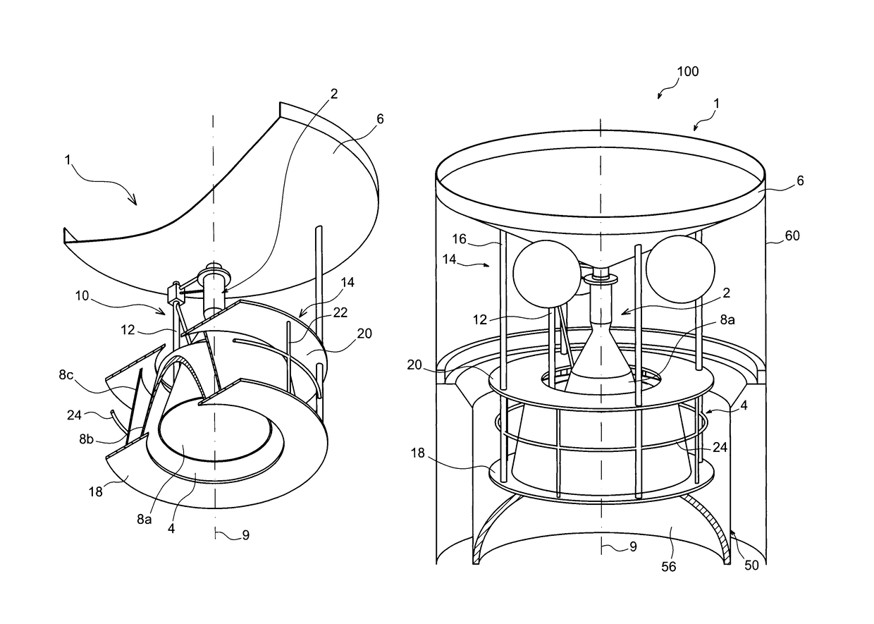
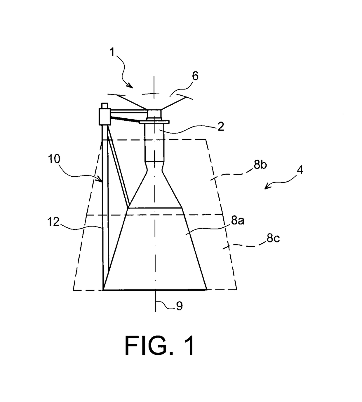
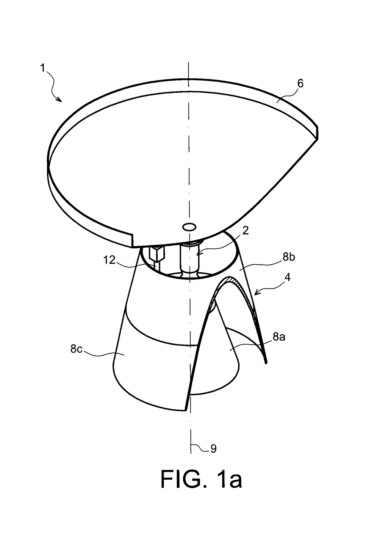
[0045]With reference to FIGS. 1, 1a and 2, a part of an upper stage of a space launcher according to one preferred embodiment of the present invention is represented, the launcher being of the Ariane 5 type.

[0046]The launcher stage 1, represented in the upright position, comprises an engine core 2 including in particular a combustion chamber wherein the reaction between liquid hydrogen and oxygen takes place, producing water vapour which is ejected at a high speed by the nozzle 4 situated below the engine core 2.

[0047]The hydrogen and oxygen are contained in a tank 6 arranged above the engine core 2, the mechanical junction between these two elements being provided using a conical tank base, as shown in FIGS. 1, 1a and 2. The payload intended to be transported by the launcher is borne above the tank 6, on this upper launcher stage.

[0048]To reduce the mass and size, the nozzle 4 has a deployable feature. It consists of three sections 8a, 8b, 8c, suitable for moving relative to each o...


PUM

PropertyMeasurementUnit
axial lengthaaaaaaaaaa
shapeaaaaaaaaaa
thrustaaaaaaaaaa

Abstract

A stage of a space launcher including an engine core, a tank secured above the engine core, and a nozzle including a first deployable nozzle section secured below the engine core, the nozzle further including a second and a third section configured to be situated extending from each other when the nozzle is in a deployed propulsion configuration. The stage further includes a structure for temporarily supporting nozzle sections mounted on the tank, configured to change the nozzle to a configuration for accessing the engine core wherein the nozzle sections are inserted into each other, with the third section bearing against a lower support of the temporary structure.

Description

FIELD OF THE INVENTION[0001]The present invention relates to the field of space launchers.[0002]More specifically, the invention relates to a space launcher comprising a main stage connected to an upper stage wherein the ejection nozzle is deployable.STATE OF THE RELATED ART[0003]On a launcher such as Ariane 5, a plurality of propulsion systems are provided. This firstly consists of two lateral powder propulsion units, used for the take-off stage, and which produce almost 90% of the thrust. After these powder propulsion units are detached to lighten the launcher, the engine of the main stage of the launcher takes over to leave the Earth's atmosphere. After the reserves thereof have been exhausted, the main stage separates from the upper stage, the engine whereof continues to provide propulsion, until the payload has been placed in orbit.[0004]The upper stage generally comprises a tank below which an engine core is attached, in turn extended downwards by an ejection nozzle. This nozz...

Claims


Application Information

Patent Timeline
Patent Type & Authority Patents(United States)
IPC IPC(8): F02K9/96B64G1/40F01D25/28F02K9/97B64G1/00
CPCF02K9/976B64G1/401F01D25/285Y10T29/49229F05D2230/68F05D2260/96B64G1/002
Inventor CONDAMINET, OLIVIERLECOMPTE, GUYMATURA, PHILIPPE
Owner SN DETUDE & DE CONSTR DE MOTEURS DAVIATION S N E C M A
Why Eureka
Try Eureka