Turbo machine with magnetic bearings

a technology of rotating shafts and bearings, which is applied in the direction of bearings, shafts, motors, etc., can solve the problems of increased outer diameter of the rotor shaft, high production costs, and high production expenditure, and achieve the effect of increasing the accuracy of position determination

Active Publication Date: 2018-06-12
ATLAS COPCO ENERGAS
View PDF6 Cites 0 Cited by
  • Summary
  • Abstract
  • Description
  • Claims
  • Application Information

AI Technical Summary

Benefits of technology

[0007]Another object is the provision of such an improved turbo machine with magnetic bearings that overcomes the above-given disadvantages, in particular whose production costs are reduced with no loss of functionality.SUMMARY OF THE INVENTION
[0008]A turbomachine has according to the invention a housing, a rotor shaft centered on an axis, and a plurality of bearings supporting the shaft in the housing for rotation about the axis. At least one of the bearings is an active magnetic bearing. An impeller is fixed on the rotor shaft. A copper layer is fixed to a surface of the rotor shaft and rotatable therewith. A sensor fixed in the housing adjacent the shaft surface can detect the copper layer and generate an output corresponding to a position of the layer relative to the housing, or more accurately from the sensor fixed in the housing. A controller connected between the sensor means and the active magnetic bearing shifts the rotor in the housing in accordance with the output.
[0010]In addition to lower production and assembly costs, the rotor dynamics can also be improved by the smaller diameter.
[0015]In order to increase the accuracy of the position determination, several gap sensors can be provided for a normally annular target, the gap sensors being angularly offset in an is annular array. Then it is also possible to calculate any faults by a difference calculation or by a comparison of the sensor signals, a certain redundancy making it possible to compensate for the failure of one sensor. Finally, it is easy to determine when one of several sensors is supplying a distorted signal.

Problems solved by technology

The production expenditure and thus the production costs are high, however, and the outer diameter of the rotor shaft is increased by the assembly of the disk unit.

Method used


Image

  • Turbo machine with magnetic bearings
  • Turbo machine with magnetic bearings
  • Turbo machine with magnetic bearings

Examples


Embodiment Construction

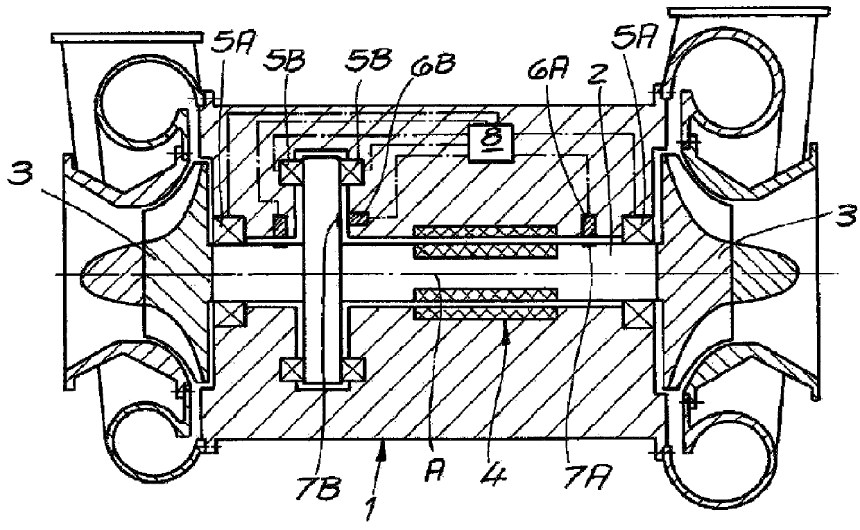
[0021]As seen in FIG. 1 a turbomachine generally comprises a housing 1 and a rotor shaft 2 supported in the housing 1 for rotation about an axis A. Here, the rotor shaft 2 carries at its opposite ends two impellers 3 that are cantilevered, that is only mounted from one side on the shaft. These impellers 3 are provided for the compression or expansion of a working fluid. Furthermore, an electric machine 4 is shown that is a generator or a motor depending on how the turbomachine is operated.

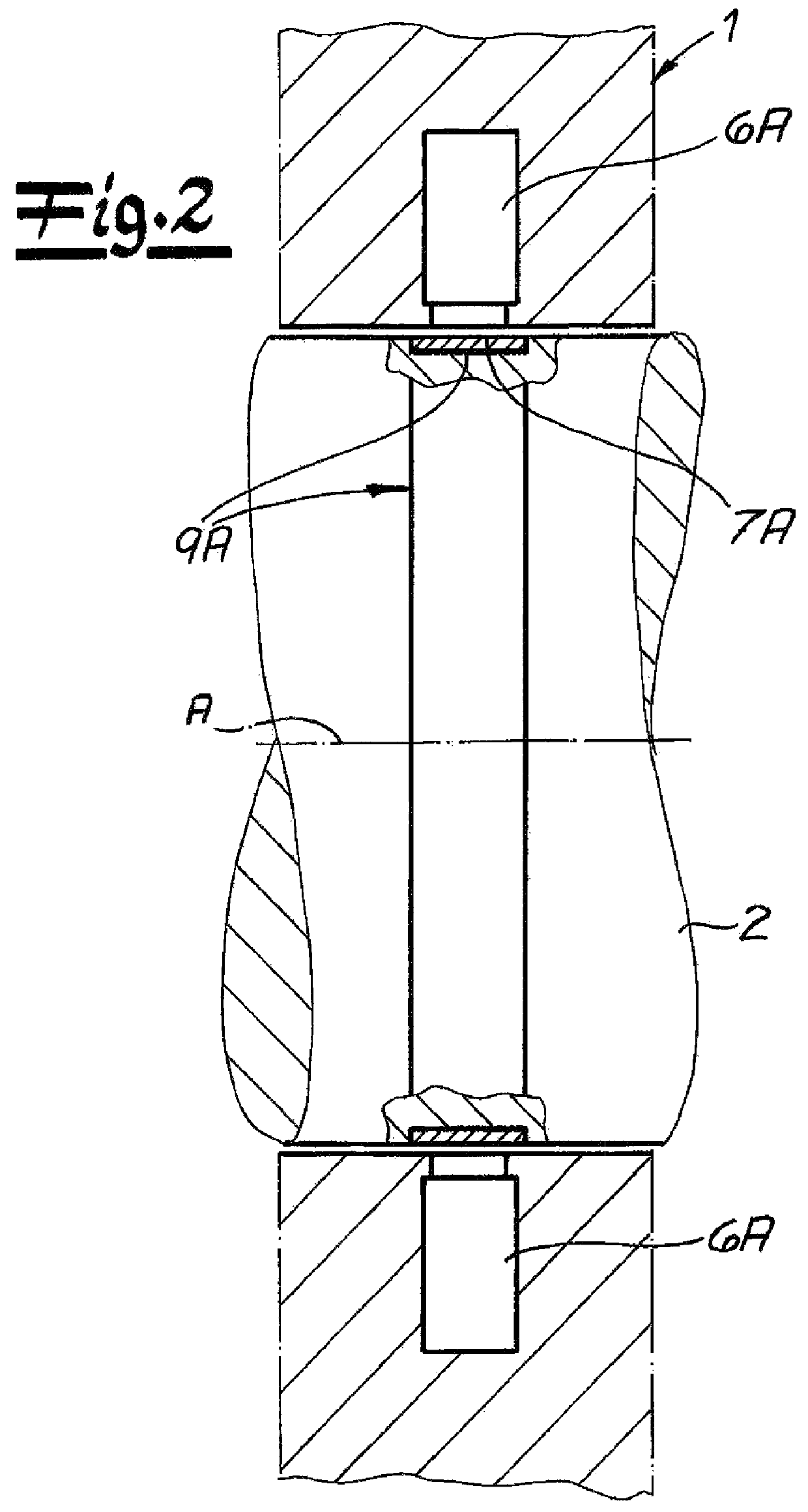
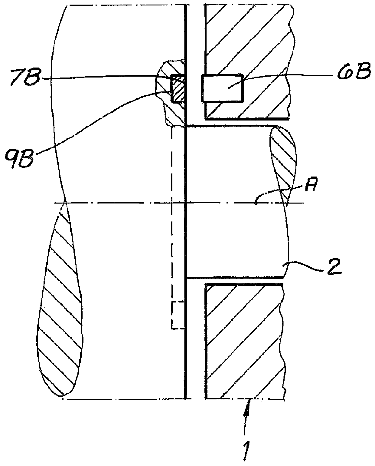
[0022]The turbomachine has a bearing assembly that in the illustrated embodiment has two active radial magnetic bearings 5A and two active axial magnetic bearings 5B. In order to be able to detect and compensate for deviations from a desired position at the magnetic bearings 5A and 5B, gap sensors 6A and 6B are provided that interact with respective targets 7A and 7B on the rotor shaft 2. The spacing between the gap sensors 6A and 6B and the respective targets 7A and 7B can be determined by gap sen...


PUM


Abstract

A turbomachine has a housing, a rotor shaft centered on an axis, and a plurality of bearings supporting the shaft in the housing for rotation about the axis. At least one of the bearings is an active magnetic bearing. An impeller is fixed on the rotor shaft. A copper layer is fixed to a surface of the rotor shaft and rotatable therewith. A sensor fixed in the housing adjacent the shaft surface can detect the copper layer and generate an output corresponding to a position of the layer from the sensor fixed in the housing. A controller connected between the sensor means and the active magnetic bearing shifts the rotor in the housing in accordance with the output.

Description

FIELD OF THE INVENTION[0001]The present invention relates to a turbomachine. More particularly this invention concerns a turbomachine whose rotor is supported on magnetic bearings.BACKGROUND OF THE INVENTION[0002]A typical turbomachine has a housing, a rotor shaft carrying at least one impeller, a bearing assembly having at least one active magnetic bearing supporting the rotor shaft in the housing, at least one gap sensor and a controller connected to the gap sensor for controlling the active magnetic bearing. In order to make it possible to precisely determine position with the gap sensor, a target interacting with the gap sensor is is provided on the rotor shaft.[0003]Magnetic bearings operate without contact and thus wear and are therefore suitable to a special extent for rapidly turning installations such as turbomachines. A gap remains between the rotor parts and confronting stator parts of the magnetic bearing, which gap is to be kept as constant as possible. In particular di...

Claims


Application Information

Patent Timeline
Patent Type & Authority Patents(United States)
IPC IPC(8): F01D25/16F04D29/058F16C32/04
CPCF16C32/0446F16C2360/24F01D25/16F04D29/048F04D29/058F05D2240/515
Inventor KOCHETOV, DMITRYWIEBE, FRANK
Owner ATLAS COPCO ENERGAS
Why Eureka
Try Eureka