Molded surface fastener

a synthetic resin and surface fastener technology, applied in the direction of snap fasteners, press-button fasteners, buckles, etc., can solve the problems of difficult to secure a predetermined degree of engaging strength, difficult to remove the hook from the hook, and the density of engaging elements on the substrate sheet surface is necessarily limited to a considerable low degree, so as to achieve the effect of convenient removal of the hook

Inactive Publication Date: 2000-07-18
YKK CORP
View PDF27 Cites 13 Cited by
  • Summary
  • Abstract
  • Description
  • Claims
  • Application Information

AI Technical Summary

Benefits of technology

It is therefore an object of this invention to provide a molded surface fastener which has engaging elements each in a rational form to improve the rate of engagement with loops and to secure a much higher increased degree of peeling strength and in which a substrate sheet can be prevented from being torn between the engaging elements.
In operation, since each of the loops entering at random between the front and rear engaging elements are parted by the parting guide member so as to come close to the front or rear engaging element, it is possible to secure a reliable engagement of the loops with the engaging elements so that the rate of engagement is increased to obtain a desired engaging force. Further, contrary to the conventional surface fasteners which are easy to be torn between rows of the engaging elements, it is possible to effectively prevent the substrate sheet from being torn since the parting guide members are integrally formed on the substrate sheet between rows of the engaging elements or between the front and rear engaging elements.
In case that the engaging element is in a form of two adjacent conventional hook elements being joined integrally with each other and having hooks facing in the opposite directions, the thickness of the stem of the engaging element of this invention is substantially double the thickness of the conventional hooked members. When a peeling force is exerted on the engaging element with both the front and rear hooks in engagement with the loops, the stem is scarcely subject to bend due to the peeling force while the individual hooks are angularly moved about their bases in a horizontal plane independently without interfering with each other and, at the same time, the upper portion of the hook resiliently deforms in the rising direction. Therefore the loops can be easily removed off the hooks without giving any damage to each other.

Problems solved by technology

However, the rigid engaging element will give an undesirable touch, and it tends to be out of engagement of the companion looped member.
In the case of the thick looped member, the surface fastener not only would become rigid but also would have less engaging elements per unit area on the substrate sheet, thus making it difficult to secure a predetermined degree of engaging strength.
Consequently the density of engaging elements on the substrate sheet surface is necessarily limited to a considerably low degree compared to the density of looped members of the companion surface fastener.
According to this arrangement, if the looped member is raised along the rear surface of the front next engaging element, there is no guarantee that the looped member may come into engagement with the hook of the rear next engaging element.
Further, with this type conventional molded surface fastener, most of the looped members entered between every adjacent pair of rows of hooks remain unengaged with the hooks.

Method used


Image

  • Molded surface fastener
  • Molded surface fastener
  • Molded surface fastener

Examples


first embodiment

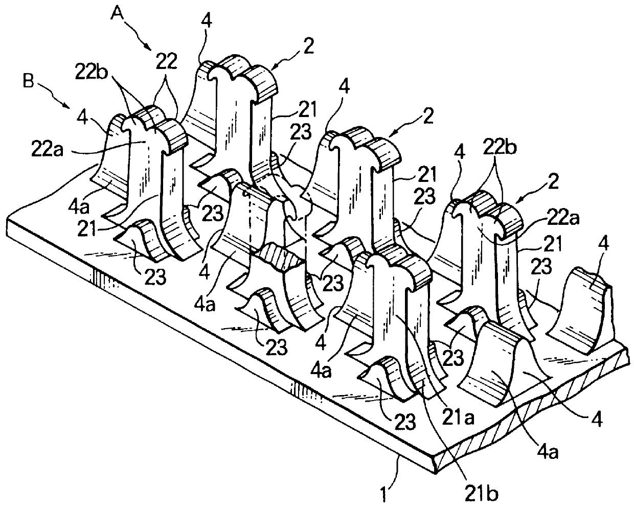
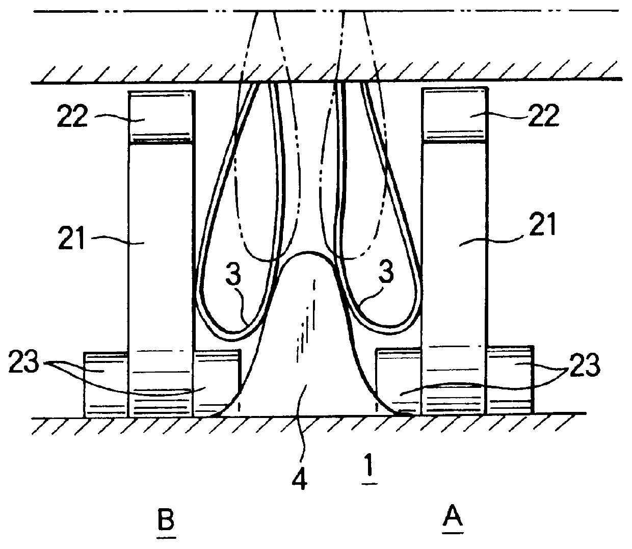
According to the molded surface fastener of the first embodiment, since the loops 3 entering at random between a multiplicity of the engaging elements 2 are parted toward the adjacent engaging elements 2 by the parting guide member 4 as shown in FIG. 2, the loopes 3 entering between the engaging element rows A, B are parted toward any of the right and left engaging element rows A, B to increase the rate of catching the loops 3 by the engaging elements 2, thus increasing the rate of engagement remarkably to obtain a predetermined engaging force. Further, contrary to the conventional surface fasteners which are easy to be torn between rows of the engaging elements, it is possible to prevent the molded surface fastener from being torn during the ejecting of the molded surface fastener from the mold or during the sewing of the molded surface fastener

or in use since the parting guide members 4 are integrally formed on the substrate sheet 1 at positions between the engaging element rows a...

second embodiment

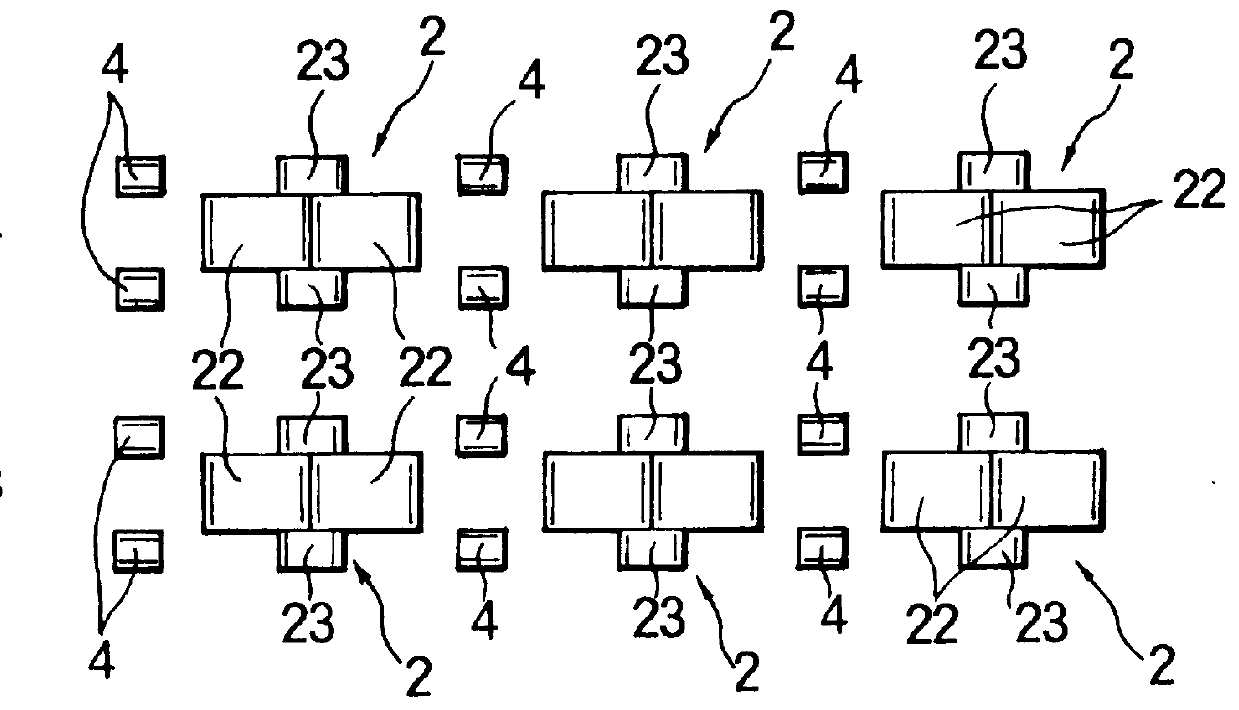
In the second embodiment, the engaging element 2 is composed of a pair of members 2-1, 2-2. Each member 2-1, 2-2 comprises a stem portions 21-1, 21-2 each having a rear surface 21c rising along a gentle curve from the upper surface of the substrate sheet 1 and a front surface 21d rising initially in a predetermined curvature and then perpendicularly from the upper surface of the substrate sheet 1 and composing a stem 21, and a hook 22 extending from the stem 21 and terminating in a downwardly directed end. The two engaging members 2-1, 2-2 are integrally joined partly at their respective hooks 22, 22 and at their respective stem portions 21-1, 21-2, as indicated by diagonal dotted lines in FIG. 7, with the hooks 22, 22 extending from the respective stem portions 21-1, 21-2 in opposite directions. In the illustrated example, each stem 21 has on its lower outside surfaces reinforcing ribs 23. A multiplicity of such engaging elements 2 are formed on the upper surface of the substrate s...


PUM

PropertyMeasurementUnit
heightaaaaaaaaaa
strengthaaaaaaaaaa
durabilityaaaaaaaaaa

Abstract

A molded surface fastener comprises a substrate sheet and a multiplicity of engaging elements molded in rows on one surface of the substrate sheet. Each of the engaging elements has a stem standing from the one surface of the substrate sheet, and a pair of hooks extending in opposite directions from a distal end of the stem. And a multiplicity of parting guide members stand from the one surface of the substrate sheet, each of which is situated centrally between adjacent engaging elements for parting loops of a companion surface fastener toward the engaging elements.

Description

BACKGROUND OF THE INVENTION1. Field of the InventionThis invention relates to a molded synthetic resin surface fastener in which a substrate sheet and a multiplicity of engaging elements projecting from one surface of the substrate sheet are formed integrally with each other, and more particularly to a molded surface fastener which has adequate engaging strength and rate suitable for use in a joint of industrial materials, such as ceiling materials and wall materials which are subject to peeling forces and which has adequate durability without giving damage to engaging elements of the companion surface fastener during peeling.2. Description of the Related ArtMolded surface fasteners of the described type have greater engaging strength compared to the ordinary knitted or woven surface fasteners and are therefore widely used in joining interior ornamental materials, such as wall materials and ceiling materials. Generally, the individual engaging element of the molded surface fastener ...

Claims


Application Information

Patent Timeline
Patent Type & Authority Patents(United States)
IPC IPC(8): A44B18/00
CPCA44B18/0061Y10T24/2792Y10T24/27A44B18/00
Inventor TAKIZAWA, TOSHIAKIMURASAKI, RYUICHI
Owner YKK CORP
Why Eureka
Try Eureka