Tufting machine with self-aligning gauging modules

a tufting machine and self-aligning technology, which is applied in the direction of embroidering machines, sewing apparatuses, textiles and paper, etc., can solve the problems of error or tolerance in positioning these gauging elements, namely needles, loopers, reeds, etc., and achieve accurate spacing

Inactive Publication Date: 2001-03-27
CARD MONROE
View PDF35 Cites 27 Cited by
  • Summary
  • Abstract
  • Description
  • Claims
  • Application Information

AI Technical Summary

Benefits of technology

Briefly described, the present invention includes a modular member having a holder or block which is cast around the end portion of a plurality of gauging elements, such as needles, loopers, and reeds which are spaced quite accurately from each other and are held in cantilever fashion so that they protrude, in appropriate alignment and gauging, from the block or holder. The blocks or holders are all of the same precise width, the back side of each holder or block being provided with a central T-shaped tab or alignment member which includes a longitudinally extending guide and a transversely extending shoulder. The longitudinally extending guides are respectively received in transversely spaced slots in gauge bars of the machine, the block and the gauge bar being provided with a pair of aligned holes through which a detent is passed when the transverse shoulder abuts an edge of the gauge bar. The slots are quite accurately, equally spaced from each other and are parallel to each other and perpendicular to a plane of a surface of the gauge bar. A plurality of such blocks are arranged along the surface of the gauge bar and are appropriately positioned on the gauge .[.bas.]. .Iadd.bar .Iaddend.so that the protruding central guides are respectively received in the slots and are quite accurately spaced from each other. The width of each block is about equal to the distance between centerlines of the adjacent slots so that the edges of the blocks abut each other.

Problems solved by technology

When building a machine, any error or tolerance in positioning these gauging elements, namely the needles, the loopers, and the reeds, may accumulate as the work progresses.

Method used


Image

  • Tufting machine with self-aligning gauging modules
  • Tufting machine with self-aligning gauging modules

Examples


Embodiment Construction

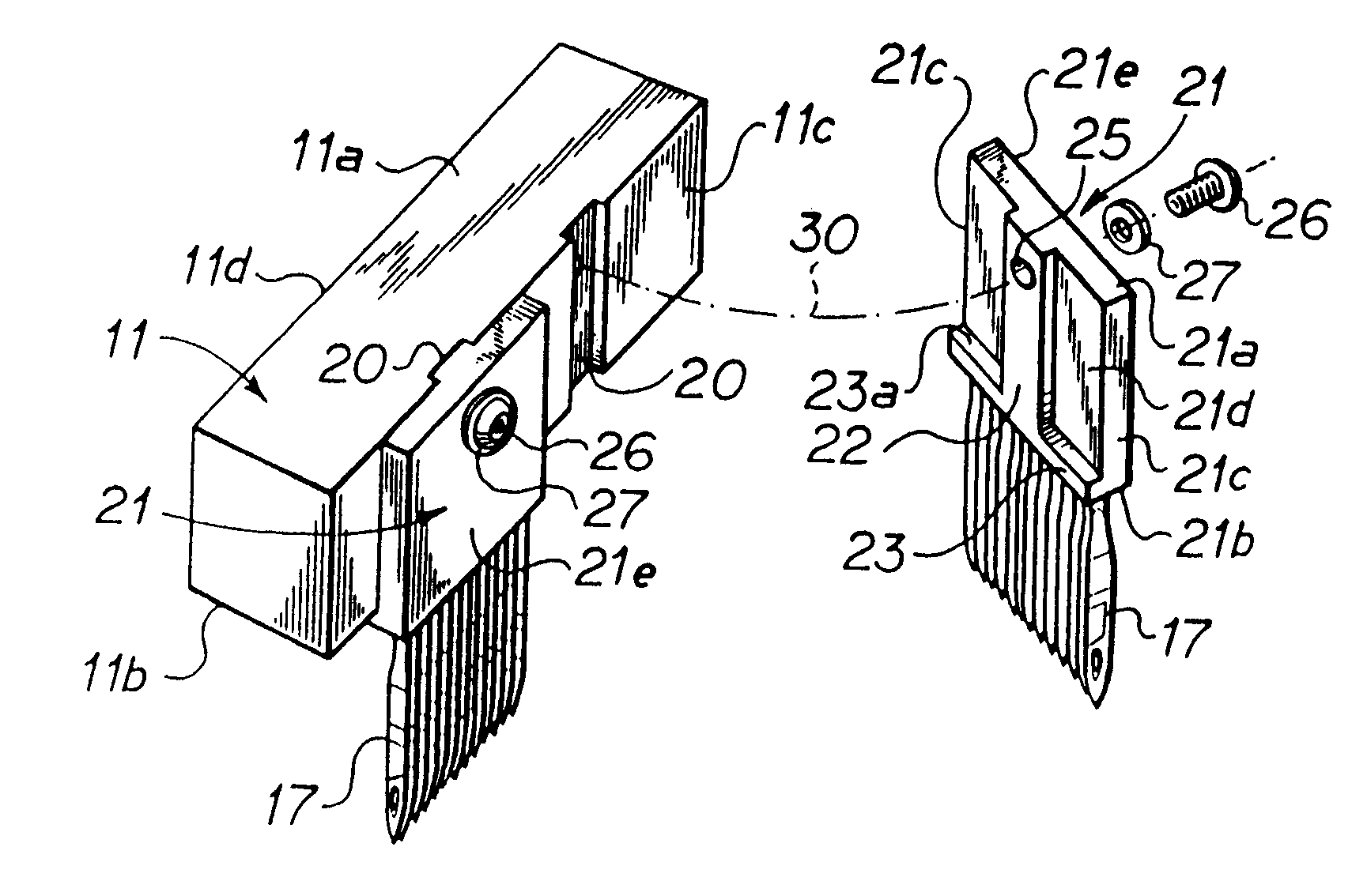
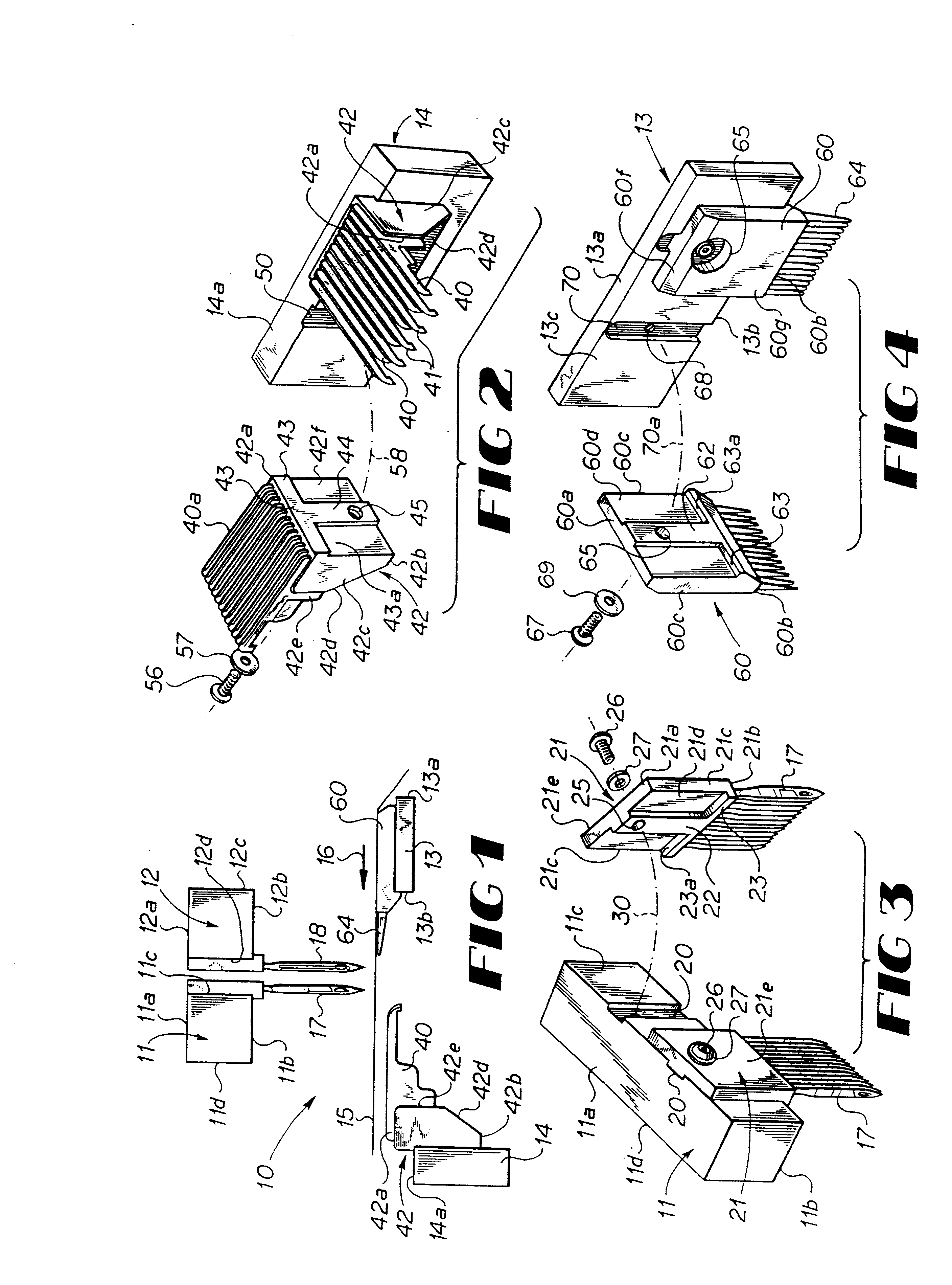
Referring now in detail to the embodiment chosen for the purpose of illustrating the present invention, numeral 10 in FIG. 1 denotes schematically the tufting zone of a cut pile tufting machine having laterally shiftable needle bars 11 and 12, a gauge bar for reed modules 13 and a looper block gauge bar 14. A backing material 15 moves across the tufting zone 10 in the direction of the arrow 16, in a conventional way. The rear needle bar 11 is adapted to support a transverse row of downwardly extending, equally spaced rear needles 17 and the front needle bar 12 is adapted to support a transverse row of equally spaced front needles 18 so that these needles 17 and 18, respectively, insert yarns (not shown) through the backing material 15 for each reciprocation of the needle bars 11 and 12 for producing transverse rows of tufts in the backing material 15. Thus, the needle bars 11 and 12 form gauge bars for supporting the blocks which carry needles 17 and 18, as will be explained hereina...


PUM


Abstract

Symmetrical, modular blocks each having a plurality of fixed, equally spaced, gauging elements, namely loopers, needles, and reeds protruding therefrom, the blocks are positioned on the sides of the guide bars of a tufting machine, each guide bar having transverse channels at equally spaced intervals. These channels respectively receive guide bars of the blocks when the blocks are removably positioned on the sides of the guide bar. Bolts or screws secure the blocks in place on their guide bars so that their needles, loopers, and reeds are appropriately gauged and positioned for tufting action, protruding toward the tufting zone.

Description

BACKGROUND OF THE INVENTIONThis invention relates to a tufting machine with self-aligning gauging modules and is more particularly concerned with a tufting machine with replaceable gauging elements which can be readily installed and removed.Tufting machines are products which must be built with precision so that the needles of the machine are accurately spaced from each other along the needle bar or bars and the loopers are accurately uniformly spaced from each other so that their bills respectively pass closely adjacent to the needles for engaging and holding loops of yarns carried by the needles. Furthermore, the spacing of the reeds must be accurate so as not to interfere with the travel of the needles. When building a machine, any error or tolerance in positioning these gauging elements, namely the needles, the loopers, and the reeds, may accumulate as the work progresses. The present invention seeks to establish a consistency for all such cross over parts throughout the machine...

Claims


Application Information

Patent Timeline
Patent Type & Authority Patents(United States)
IPC IPC(8): D05C15/22D05C15/20D05C15/00D05C15/16
CPCD05C15/20D05C15/22
Inventor NEELY, MARSHALL ALLEN
Owner CARD MONROE
Why Eureka
Try Eureka