Connector guide member

a technology of guide member and connector, which is applied in the direction of coupling device connection, coupling prevention, engagement/disengagement of coupling parts, etc., can solve the problems of adding cost to the assembly process of electronic devices using connectors and cages, and achieve the effect of convenient mounting on the circuit board

Active Publication Date: 2006-08-24
MOLEX INC
View PDF25 Cites 33 Cited by
  • Summary
  • Abstract
  • Description
  • Claims
  • Application Information

AI Technical Summary

Benefits of technology

[0005] Accordingly, it is a general object of the present invention to provide a connector and shroud, or guide member, that are easily mounted to a circuit board by automated means.

Problems solved by technology

This adds cost to the assembly process of the electronic device the connector and cage are used in.

Method used


Image

  • Connector guide member
  • Connector guide member
  • Connector guide member

Examples


Embodiment Construction

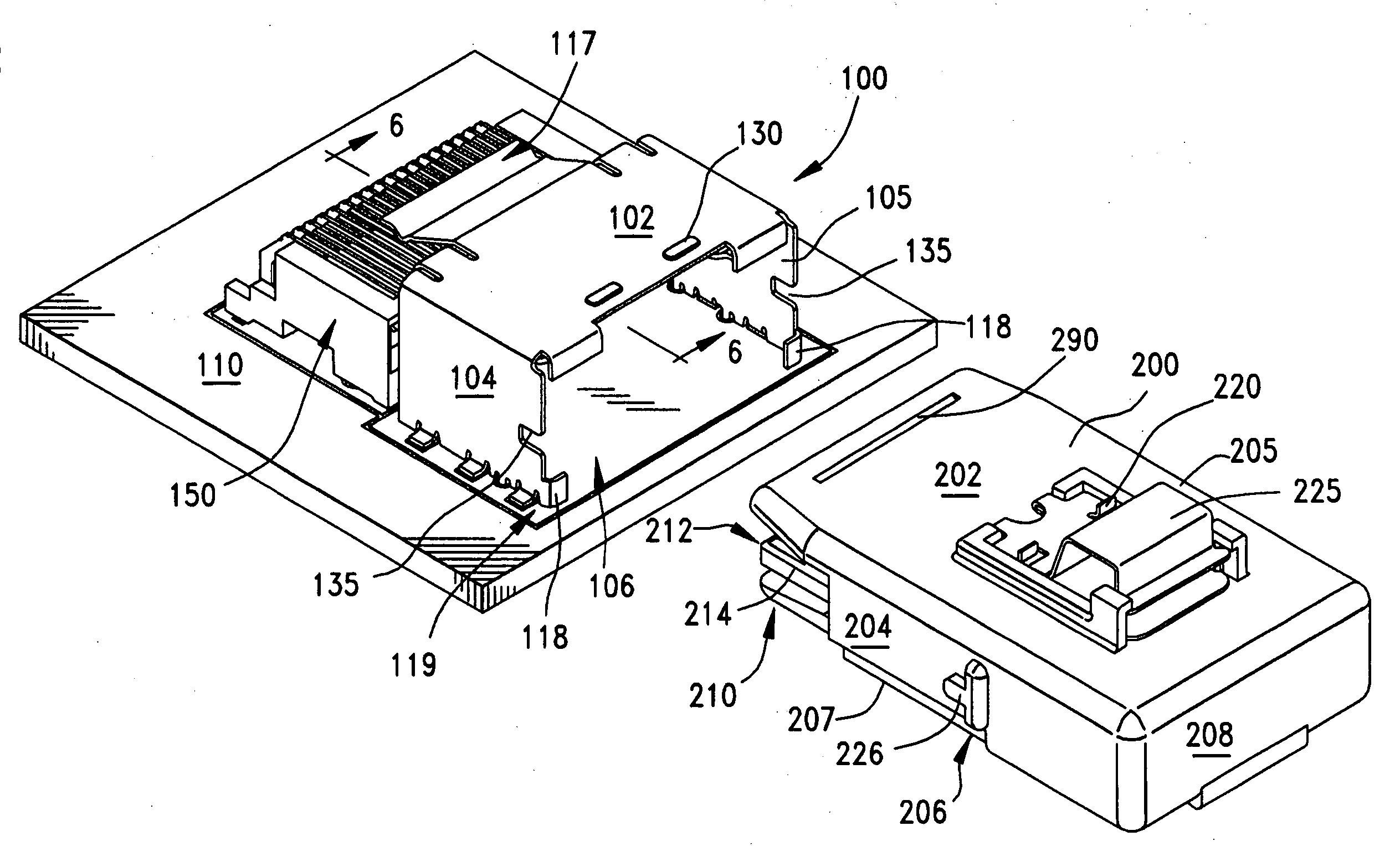
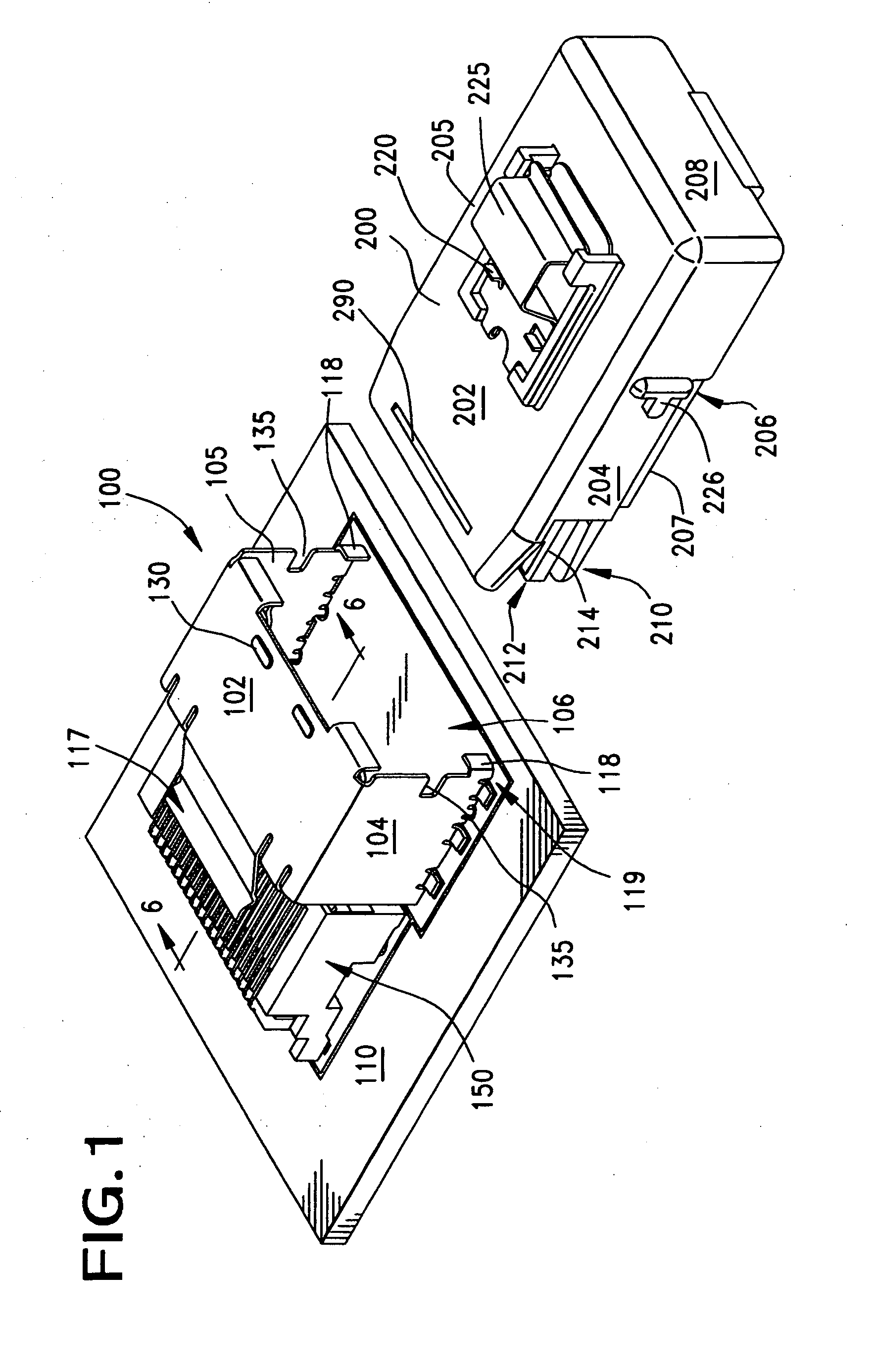
[0039]FIG. 1 illustrates a first embodiment of the invention, namely a shroud, or guide 100, having a top wall 102 and two spaced-apart sidewalls 104.105. The shroud 100 has a general inverted U-shape when viewed from an end, and when placed on a circuit board 110 spaced apart from a connector 150 mounted to the circuit board 110. The shroud 100 provides a hollow channel 106 that may guide an opposing (plug-style) connector 200 into engagement with the circuit board connector 150. The shroud 100 also serves to retain the mating connector 200 in place.

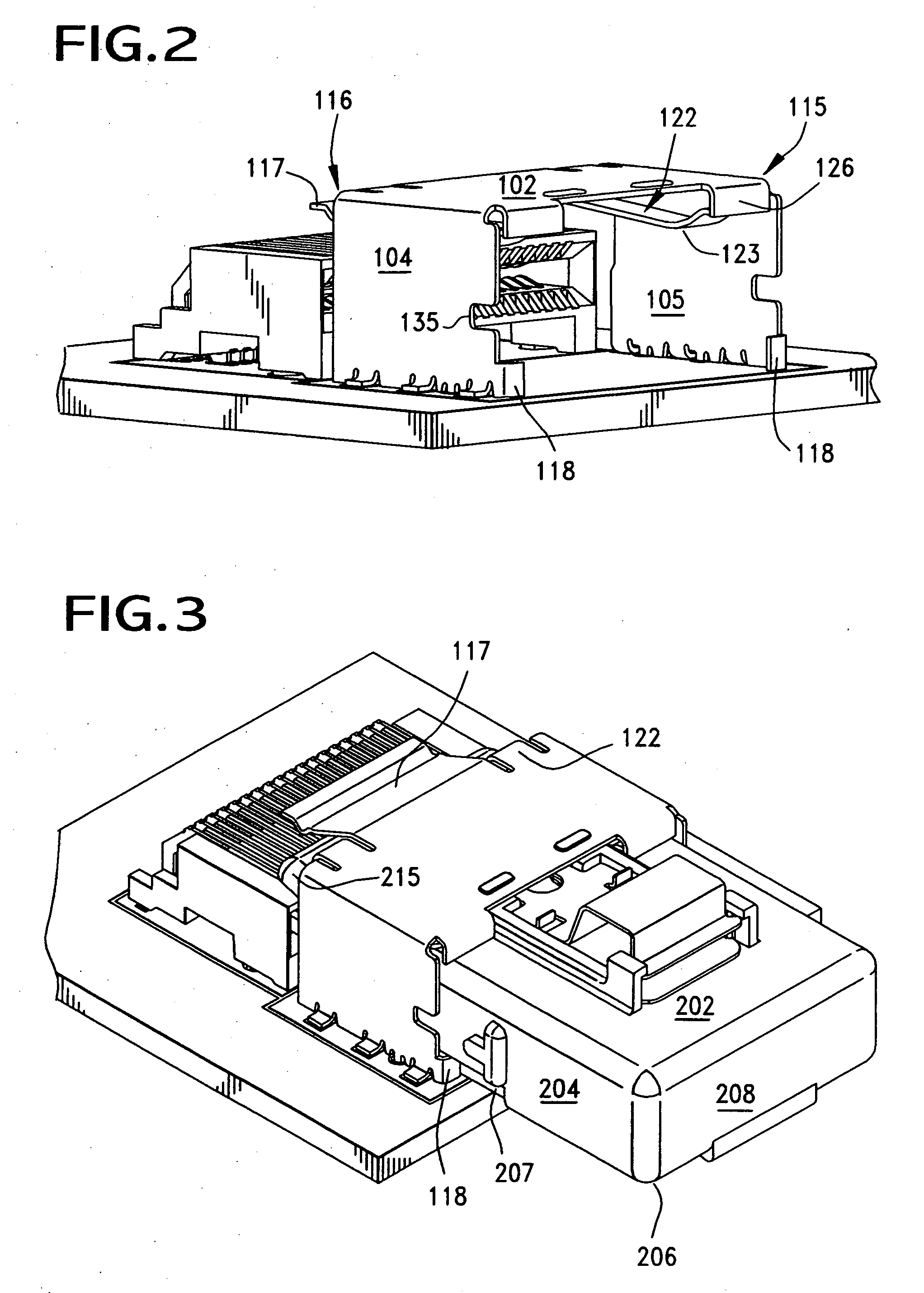
[0040] As shown in FIGS. 2 & 6A, the shroud 100 has a front face 115 and a rear face 116. A press tab, or press arm 117, is formed with the shroud 100, and the tab 117 extends outwardly from the shroud 100 along the rear face 116 in a cantilevered fashion. (FIG. 6A.) The purpose of this press tab 117 is to engage an upper surface 202, preferably a channel, or recess 290, of the mating connector 200 when it is inserted into the interior...


PUM


Abstract

A shroud that forms a guide channel for a connector is disclosed and it has the shape of an inverted U-shape, with a press tab for engaging a mating connector. The shroud has notches and tabs formed on it that serve to orient the mating connector for entry into the shroud. A placement member is also described and it serves to hold the connector and the shroud together as a single unit for robotic placement of the shroud and connector in preselected positions on the circuit board.

Description

BACKGROUND OF THE INVENTION [0001] The present invention relates generally to connector shrouds, and more particularly to a shroud and placement member that cooperate as an engaged assembly for mounting the shroud and an associated connector on a circuit board. [0002] Most small form factor pluggable style connectors are surface mounted to a circuit board and then are enclosed in a metal or metallic shielding cage. The use of this external cage requires that the connector be first mounted to a circuit board, and then the cage must be mounted to the circuit board. Many times the connector may be of a surface mount style, while the shielding cage is of a press fit style, meaning that each of the two components must be separately applied to the circuit board. This adds cost to the assembly process of the electronic device the connector and cage are used in. [0003] In order to speed the assembly process and to reduce the costs involved, it is desirable that the connector and cage someho...

Claims


Application Information

Patent Timeline
Patent Type & Authority Applications(United States)
IPC IPC(8): H01R13/64H01R12/71
CPCH01R12/7005
Inventor LANG, HAROLD KEITHBANAKIS, EMANUEL G.REGNIER, KENT E.SWENSON, JENNIFER
Owner MOLEX INC
Why Eureka
Try Eureka