Individual transport control and communication system

a communication system and individual technology, applied in the field of vehicle control and communication system, can solve the problems of congestion, waste of time and excessive fuel consumption, and inability to accept congestion, and achieve the effect of maximizing the throughput of vehicles

Inactive Publication Date: 2007-10-23
CASCADE ENG
View PDF11 Cites 35 Cited by
  • Summary
  • Abstract
  • Description
  • Claims
  • Application Information

AI Technical Summary

Benefits of technology

[0005]One aspect of the present invention is to provide a method for controlling a plurality of vehicles along a pathway that includes monitoring a location and a speed of each of a plurality of vehicles with respect to a pathway via an on-board monitoring system within each vehicle, transmitting, a signal that includes the location and the speed of each vehicle directly to each of the other vehicles via an on-board transmitter within each vehicle, and receiving the signal directly from the other vehicles via an on-board receiver within each vehicle. The method also includes controlling each of the vehicles via an on-board controller within each vehicle based on the signal received from each of the other vehicles to provide proper spacing between the vehicles, to avoid collisions therebetween and maximize throughput of the vehicles along the pathway.
[0006]Another aspect of the present invention is to provide an automated transportation system that includes a plurality of vehicles adapted to travel along a pathway, and a monitoring system located within each vehicle and adapted to monitor a location and a speed between an associated vehicle and the pathway. The automated transportation system also includes a transmitter located within each vehicle and adapted to transmit a signal that includes data on the location and the speed monitored, and a receiver located within each vehicle and adapted to receive the signal from each vehicle. The automated transportation system further includes a controller located within each vehicle and adapted to interpret the signal received by the receiver from each of the other vehicles and control the associated vehicle to provide proper spacing between the remaining vehicles to avoid collisions therebetween and maximize throughput of the vehicles along the pathway.
[0007]Yet another aspect of the present invention is to provide a method for controlling a vehicle along a pathway that includes monitoring a speed and a location of each of a plurality of vehicles with respect to a pathway via a monitoring system located within each vehicle, and transmitting a primary signal that includes the speed and location of each vehicle directly from each vehicle to each of the other vehicles via a transmitter located within each vehicle. The method also includes receiving the primary signal directly from the other vehicles via a receiver located within each vehicle, receiving the primary signal at a central controller, and receiving a secondary signal from the central controller via the receiver located within each vehicle. The method further includes controlling each of the vehicles via a vehicle control system located within each vehicle based on the primary signal received from each of the other vehicles to provide proper spacing between the vehicles to avoid collisions therebetween and maximize throughput of the vehicles along the pathway, and controlling each of the vehicles via the vehicle control system located within each vehicle based on the secondary signal received from the central controller if the primary signal is interfered with to provide proper spacing between the vehicles to avoid collisions therebetween and maximize throughput of the vehicles along the pathway.

Problems solved by technology

Ever increasing demands on conventional individual transportation modes has led to unacceptable congestion.
Such congestions have led to unacceptable delays resulting both in waste of time and excessive fuel consumption.
The congestion problems are exacerbated by poor traffic management within particular concentrated areas, as well as within entire highway / roadway systems.
Unfortunately, differences in driving skills and levels of responsibility can cause serious injuries or even fatalities.
The most significant drawback with respect to these mass transits systems is the inconveniences associated with their schedules to pre-determined destinations.
With heavy usage and the commonly-applied principal of first-come-first-served, people might not have an available seat, or personal space to work in or relax.
Mass transit systems are also required to operate at off-peak hours with minimal usage making them expensive to operate.

Method used


Image

  • Individual transport control and communication system
  • Individual transport control and communication system
  • Individual transport control and communication system

Examples


Embodiment Construction

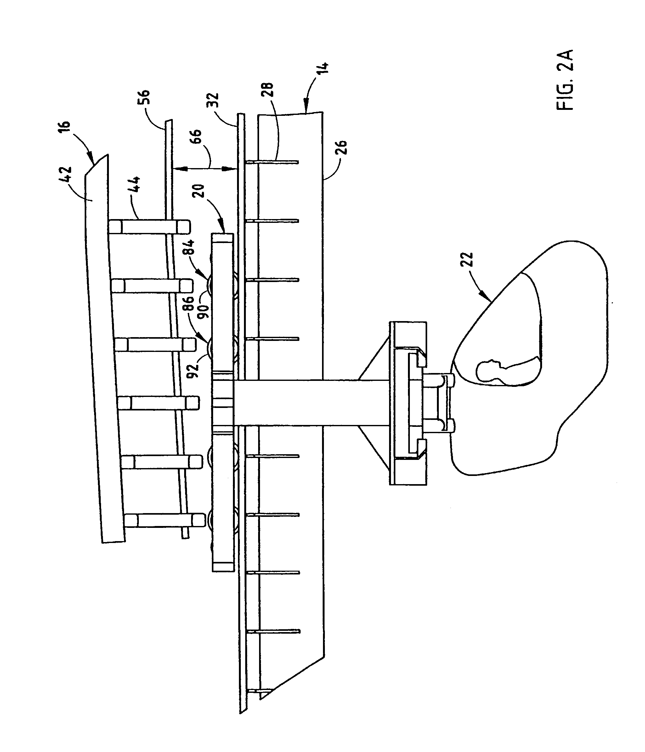
[0028]For purposes of description herein, the terms “upper,”“lower,”“right,”“left,”“rear,”“front,”“vertical,”“horizontal,” and derivatives thereof shall relate to the invention as oriented in FIG. 2A. However, it is to be understood that the invention may assume various alternative orientations and step sequences, except where expressly specified to the contrary. It is also to be understood that the specific devices and processes illustrated in the attached drawings, and described in the following specification are exemplary embodiments of the inventive concepts defined in the appended claims. Hence, specific dimensions and other physical characteristics relating to the embodiments disclosed herein are not to be considered as limiting, unless the claims expressly state otherwise.

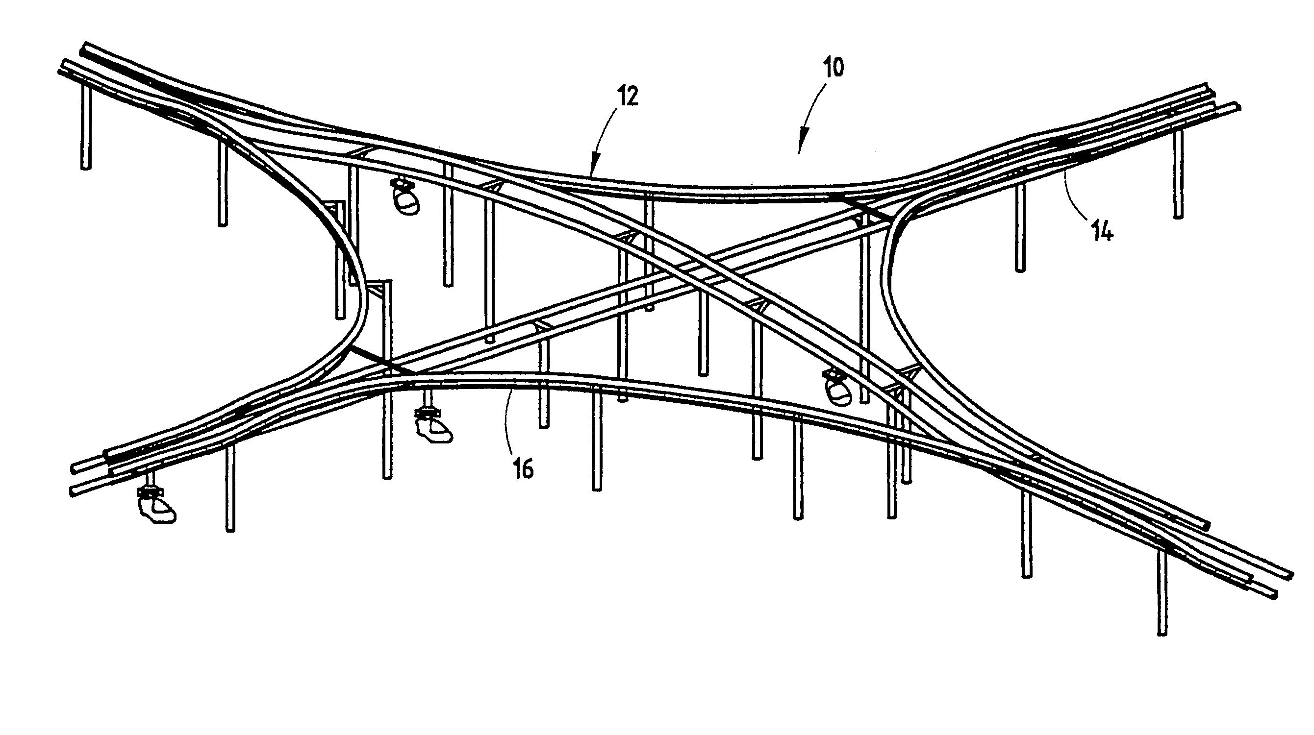
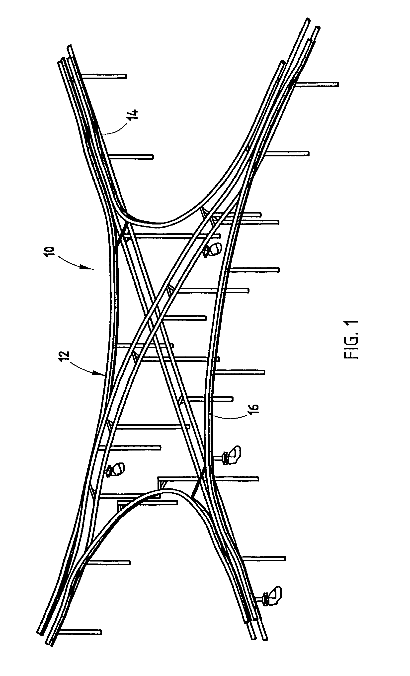
[0029]In the illustrated example, the present inventive individual transport control and communication system is utilized in conjunction with an individual transportation system 10 (FIG. 1). It should be not...


PUM


Abstract

An automated transportation (10) system includes a plurality of vehicles (22) adapted to travel along a pathway, and a monitoring system (70) located within each vehicle and adapted to monitor a location and a speed between an associated vehicle and the pathway. The automated transportation system (10) also includes a transmitter (72) located within each vehicle (22) and adapted to transmit a signal that includes data on the location and the speed monitored, and a receiver (76) located within each vehicle and adapted to receive the signal from each of the other vehicles. The automated transportation system (10) further includes a controller (78) located within each vehicle and adapted to interpret the signal received by the receiver and control the associated vehicle to provide proper spacing between the remaining vehicles to avoid collisions therebetween and maximize throughput of the vehicles along the pathway.

Description

BACKGROUND OF THE INVENTION[0001]The present invention relates to a vehicle control and communication system, and in particular to a vehicle control and communication system that controls the speed of a vehicle along a pathway relative to the position and speed of other vehicles traveling along the pathway.[0002]Ever increasing demands on conventional individual transportation modes has led to unacceptable congestion. Expanding populations, most noticeably in urban areas, have begun to over tax our city streets and highway systems designed to support a fraction of the vehicular traffic currently using them. Such congestions have led to unacceptable delays resulting both in waste of time and excessive fuel consumption. The congestion problems are exacerbated by poor traffic management within particular concentrated areas, as well as within entire highway / roadway systems. In addition, individual traffic as currently organized, depends on each person to drive his or her vehicle safely ...

Claims


Application Information

Patent Timeline
Patent Type & Authority Patents(United States)
IPC IPC(8): G06G7/78B60K31/00B60L15/40B60LB60L13/00B61L27/04G01M17/013G01S1/00G06FG06F17/10G08G1/052G08G1/133G08G1/16
CPCG05D1/0287B61L27/04B60W2050/046B60W2050/048G06Q50/30
Inventor GAEGAUF, BENEDIKT J.AMMOND, P. CHARLES
Owner CASCADE ENG
Why Eureka
Try Eureka