Downhole Barrier Valve

a barrier valve and hole technology, applied in the direction of fluid removal, borehole/well accessories, construction, etc., can solve the problem of limited length of surface lubricators, and achieve the effect of preventing leakag

Active Publication Date: 2008-09-18
BAKER HUGHES INC
View PDF33 Cites 35 Cited by
  • Summary
  • Abstract
  • Description
  • Claims
  • Application Information

AI Technical Summary

Benefits of technology

[0009]A ball type downhole barrier valve capable of bidirectional sealing features a ball rotating on its axis to open or close with control line pressure to an actuating rod piston assembly. The ball is also shiftable to a locked open position. A cage surrounds the ball and retains opposed seats to it. The cage is made from one piece and tangential holes are drilled and tapped before the piece is longitudinally split with a wire EDM cutting technique. Fasteners to rejoin the cut halves properly space them to the original one piece internal dimension. Auxiliary tools allow determination of spacing of internal components so that a desired spring preload on the seats against the ball can be achieved. Seals on the sleeves that form ball seats help prevent leakage due to ball distortion at high differential pressures when the valve is closed.

Problems solved by technology

These surface lubricators have limited lengths determined by the scale of the available rig equipment.

Method used


Image

  • Downhole Barrier Valve
  • Downhole Barrier Valve
  • Downhole Barrier Valve

Examples


Embodiment Construction

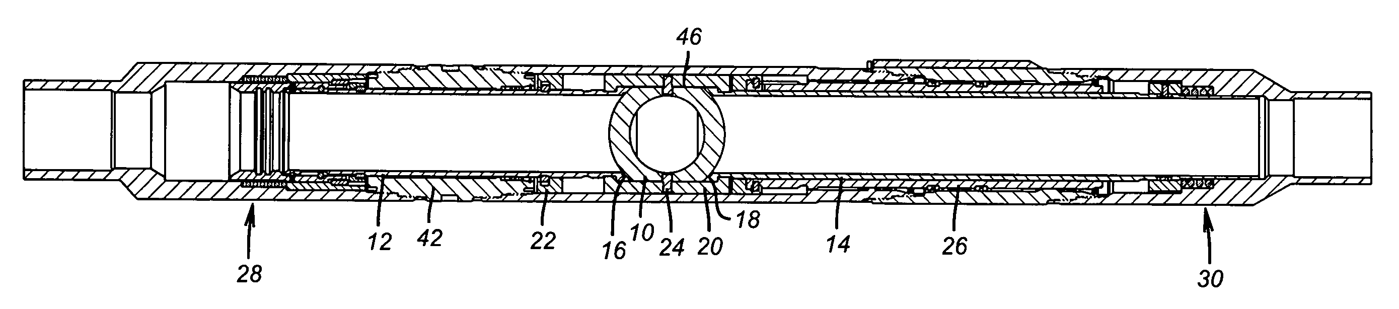
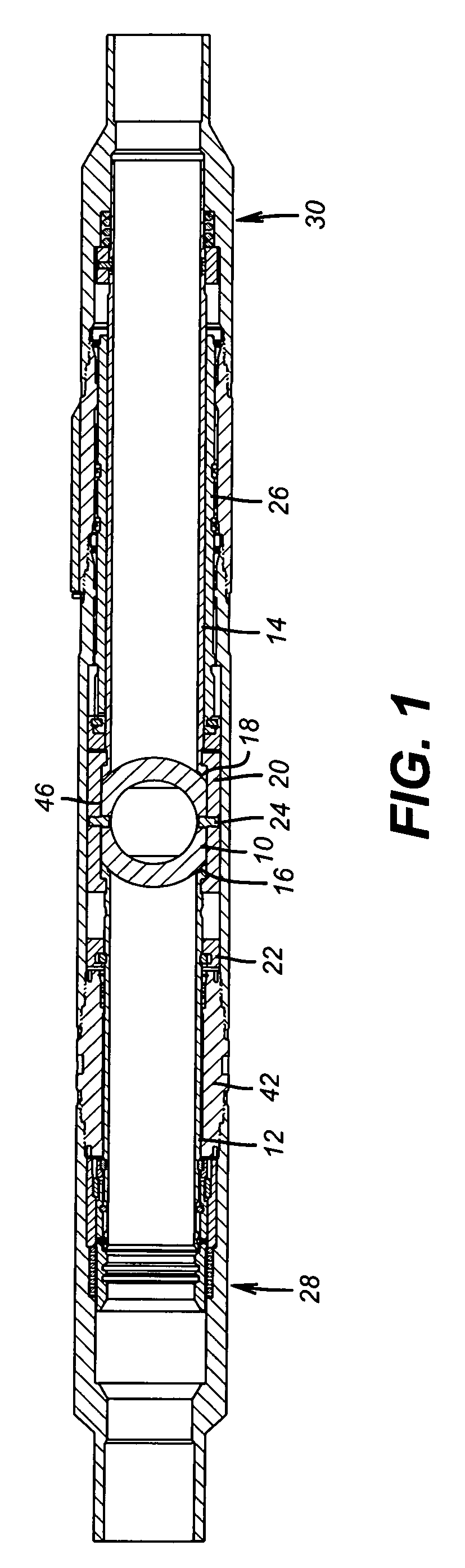
[0025]FIG. 1 illustrates the layout of the main components to show their position relative to each other with the ball 10 in the center and in the closed position. Sleeve 12 is above ball 10 and sleeve 14 is below ball 10. These sleeves respectively form seats 16 and 18 that are held against ball 10 by a cage 20. Cage 20 is shown in perspective in FIG. 9. A slide 22 extends through cage 20 and registers with ball 10 to rotate it between the open and closed position on trunnions 24. A piston 26 is responsive to control line pressure to reciprocate the slide 22 to operate ball 10. A lock open assembly 28 is disposed near the top of the tool while the preload adjustment mechanism 30 is located near the opposite end. Using this basic locating of the major components of the valve, the other FIGS. will now be used to bring out additional details and explain the basic operation.

[0026]FIG. 6 can be used to appreciate how the ball 10 is rotated 90 degrees between the closed position shown in...


PUM


Abstract

A ball type downhole barrier valve capable of bidirectional sealing features a ball rotating on its axis to open or close with control line pressure to an actuating rod piston assembly. The ball is also shiftable to a locked open position. A cage surrounds the ball and retains opposed seats to it. The cage is made from one piece and tangential holes are drilled and tapped before the piece is longitudinally split with a wire EDM cutting technique. Fasteners to rejoin the cut halves properly space them to the original one piece internal dimension. Auxiliary tools allow determination of spacing of internal components so that a desired spring preload on the seats against the ball can be achieved. Seals on the sleeves that form ball seats help prevent leakage due to ball distortion at high differential pressures when the valve is closed.

Description

RELATED APPLICATIONS[0001]This application is a continuation in part of U.S. application Ser. No. 11 / 595,596 filed on Nov. 9, 2006 and having the title Downhole Lubricator Valve.FIELD OF THE INVENTION[0002]The field of the invention relates to downhole barrier valves such as, among other applications, a valve for forming a downhole lubricator that allow a string to be made up in a live well by isolation of a lower portion of it and more particularly to features regarding such valves relating to locking them, assembling them and component fabrication techniques.BACKGROUND OF THE INVENTION[0003]Lubricator valves are valves used downhole to allow long assemblies to be put together in the well above the closed lubricator valve with well pressure further below the closed lubricator valve. These valves are frequently used in tandem with sub-surface safety valves to have redundancy of closures against well pressures below. Valves are also used downhole for other isolation purposes.[0004]Lu...

Claims


Application Information

Patent Timeline
Patent Type & Authority Applications(United States)
IPC IPC(8): E21B34/08
CPCE21B2034/002E21B34/103E21B2200/04E21B34/10E21B34/14E21B43/12
Inventor BEALL, CLIFFORD H.MAY, MICHAEL J.SLOAN, JAMES T.HAYNES, ANDREWANDREWS, THAD D.
Owner BAKER HUGHES INC
Why Eureka
Try Eureka