Connector guide member
a technology of guide member and connector, which is applied in the direction of coupling device connection, coupling prevention, engagement/disengagement of coupling parts, etc., can solve the problems of adding cost to the assembly process of electronic devices using connectors and cages, and achieve the effect of convenient mounting on the circuit board
- Summary
- Abstract
- Description
- Claims
- Application Information
AI Technical Summary
Benefits of technology
Problems solved by technology
Method used
Image
Examples
Embodiment Construction
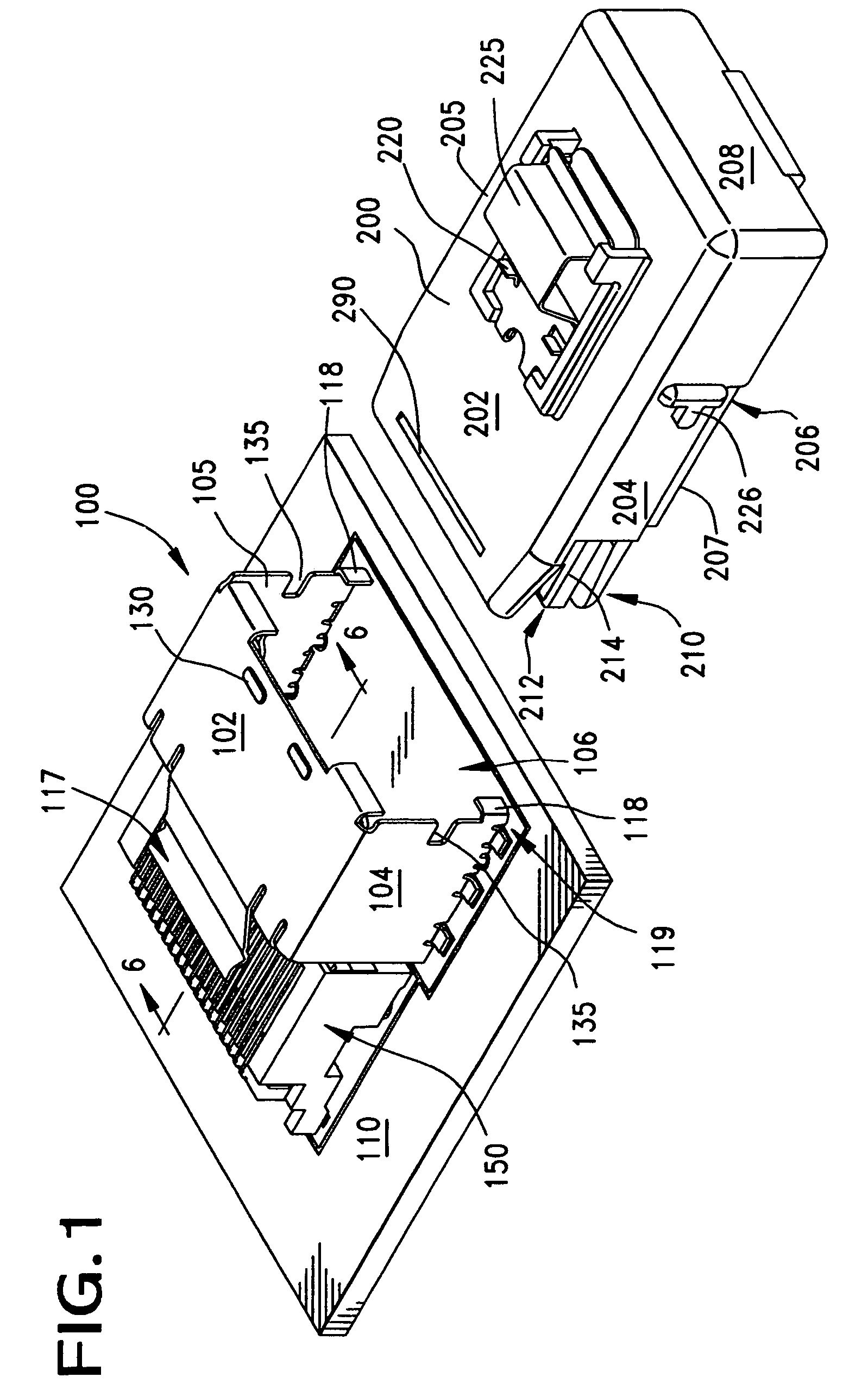
[0040]FIG. 1 illustrates a first embodiment of the invention, namely a shroud, or guide 100, having a top wall 102 and two spaced-apart sidewalls 104.105. The shroud 100 has a general inverted U-shape when viewed from an end, and when placed on a circuit board 110 spaced apart from a connector 150 mounted to the circuit board 110. The shroud 100 provides a hollow channel 106 that may guide an opposing (plug-style) connector 200 into engagement with the circuit board connector 150. The shroud 100 also serves to retain the mating connector 200 in place.
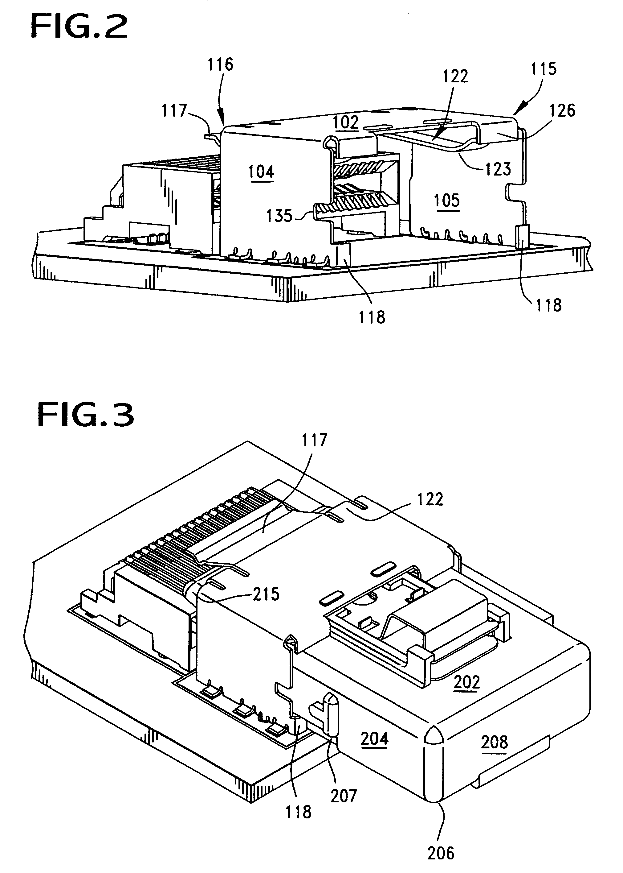
[0041]As shown in FIGS. 2 & 6A, the shroud 100 has a front face 115 and a rear face 116. A press tab, or press arm 117, is formed with the shroud 100, and the tab 117 extends outwardly from the shroud 100 along the rear face 116 in a cantilevered fashion. (FIG. 6A.) The purpose of this press tab 117 is to engage an upper surface 202, preferably a channel, or recess 290, of the mating connector 200 when it is inserted into the interior c...
PUM
 Abstract
Description
Claims
Application Information
 - R&D
- Intellectual Property
- Life Sciences
- Materials
- Tech Scout
- Unparalleled Data Quality
- Higher Quality Content
- 60% Fewer Hallucinations
Browse by: Latest US Patents, China's latest patents, Technical Efficacy Thesaurus, Application Domain, Technology Topic, Popular Technical Reports.
© 2025 PatSnap. All rights reserved.Legal|Privacy policy|Modern Slavery Act Transparency Statement|Sitemap|About US| Contact US: help@patsnap.com


