Anterior spinal instrumentation and method for implantation and revision

a spinal instrument and anterior spinal technology, applied in the field of spinal instrumentation system, can solve the problems of significant compromise of vertebral body, loss of reduction or correction, and loss of correction, and achieve the effect of enhancing rigidity and fixation, and more reliable and complete decompression of spinal canals

Inactive Publication Date: 2001-05-01
MICHELSON GARY K +1
View PDF8 Cites 368 Cited by
  • Summary
  • Abstract
  • Description
  • Claims
  • Application Information

AI Technical Summary

Benefits of technology

In accordance with the method, bone screws are engaged within the vertebral bodies of the intermediate vertebrae. Preferably, the bone screws are variable angle screws having a cancellous threaded portion that is long enough to engage both lateral cortices of the respective vertebrae. An attachment member is provided having a head portion configured substantially similar to the head portion of the variable angle screw. In the preferred embodiment, eyebolt assemblies are used to attach and fix the head portions of the variable angle screws and the attachment members to an elongated spinal rod. The rod is positioned posteriorly of the head portions and is offset from the longitudinal axis of the fusion implant. It has been found that this anterior system and surgical technique provides a more reliable and complete decompression of the spinal canal. The use of the fusion devices as anchors at the ends of the construct renders this anterior instrumentation a viable alternative to address spinal conditions previously reserved for treatment from a posterior approach.
The system in accordance with one embodiment utilizes a threaded cylindrical fusion implant that is placed between or threaded into the endplates of the adjacent vertebrae. The implant can be filled with morcellized autologous bone to promote fusion through the implant and between the vertebral endplates. One end of the fusion implant is laterally disposed and accessible for placement of an attachment member. In one embodiment, the exposed end has a threaded opening for receiving a threaded post of the attachment member. In accordance with one feature of the present invention, the attachment member also includes a head portion that is configured substantially similar to the head of the bone screw engaged in the intermediate vertebrae. The head portion defines a slot for receiving the body of an eyebolt assembly, and includes a pattern of radial serrations. The head portions of the fusion implant attachment members and the bone screws are engaged to the spinal rod by a variable angle connection member comprising an eyebolt, nut and splined washer. The attachment member provides a significant benefit in that it adapts a known fusion implant to appear and behave as a bone screw with enhanced rigidity and fixation.
It is one object of the present invention to present a novel method for anterior instrumentation of the spine. A further object resides in features of the anterior technique and the implant system itself that provides a rigid and secure fixation of the spine, especially at the cephalad and caudal extremes of the system.

Problems solved by technology

Initially, the anterior approach to spinal instrumentation, that is from the front and side of the patient, was not favored, due to the unfamiliarity of this approach to spinal surgeons and due to the fear of severe complications, such as neurovascular injury or compromise of the spinal cord.
However, in the face of some reported difficulties in addressing correction of thoracolumbar and lumbar scoliotic curvatures from a posterior approach, surgeons sought anterior forms of correction and stabilization.
Many of these anterior systems can lead to complications.
Some of the more prominent problems that have occurred involve failure of the fixation components, and an often high incidence of loss of reduction or correction.
Many of the difficulties in this respect can be traced to the vertebrae instrumented at the end of the construct where the loads on the instrumentation are the greatest.
In addition, the system must ensure a strong fixation that will not deteriorate over time resulting in a loss of correction.
In systems using bone screws, revision surgeries can significantly compromise the vertebral body.
In addition, in certain anterior approaches where stronger fixation is essential, revision procedures to replace failed components may necessarily compromise the new construct.

Method used


Image

  • Anterior spinal instrumentation and method for implantation and revision
  • Anterior spinal instrumentation and method for implantation and revision
  • Anterior spinal instrumentation and method for implantation and revision

Examples


Embodiment Construction

For the purposes of promoting an understanding of the principles of the invention, reference will now be made to the embodiments illustrated in the drawings and specific language will be used to describe the same. It will nevertheless be understood that no limitation of the scope of the invention is thereby intended, such alterations and further modifications in the illustrated device, and such further applications of the principles of the invention as illustrated therein being contemplated as would normally occur to one skilled in the art to which the invention relates.

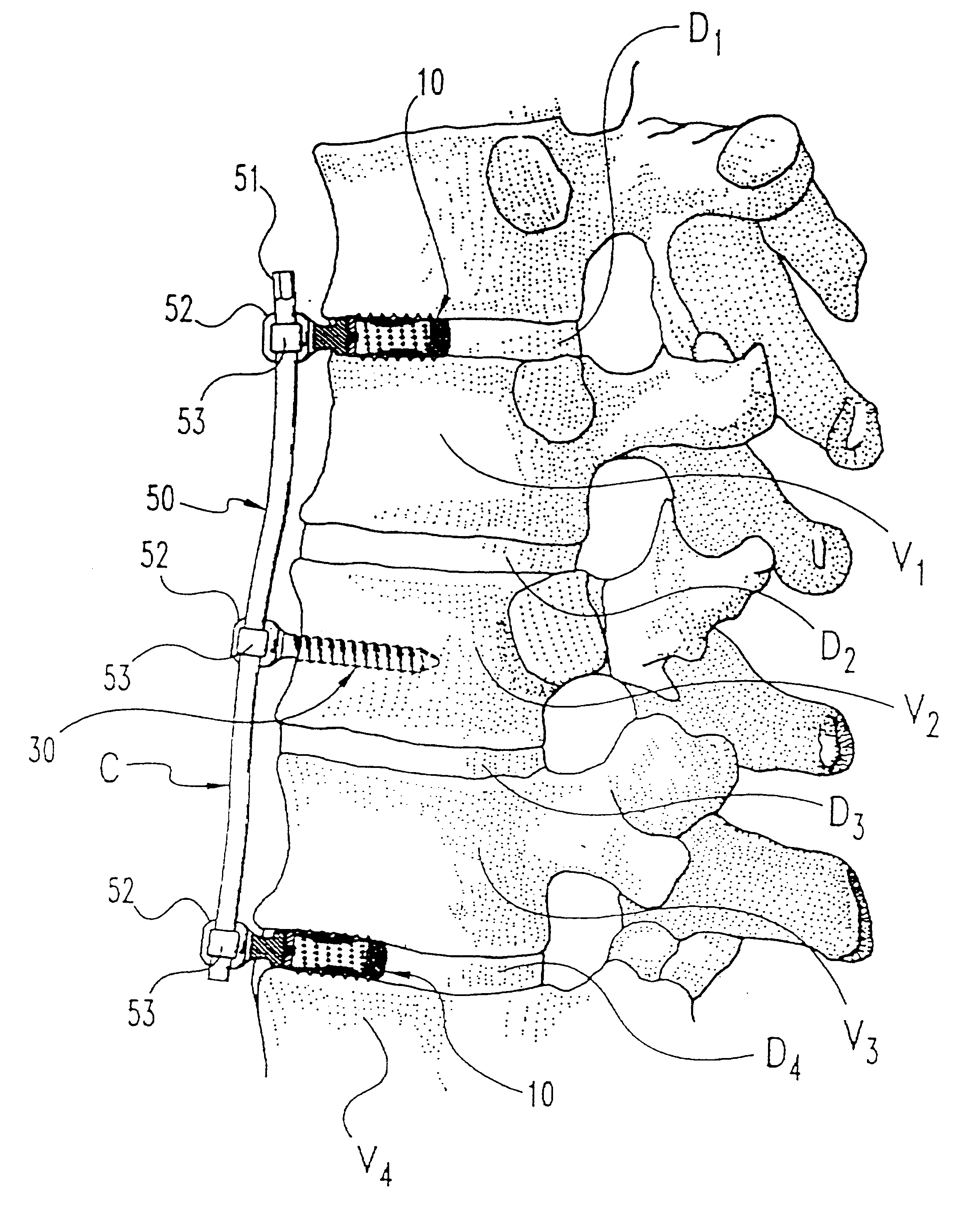
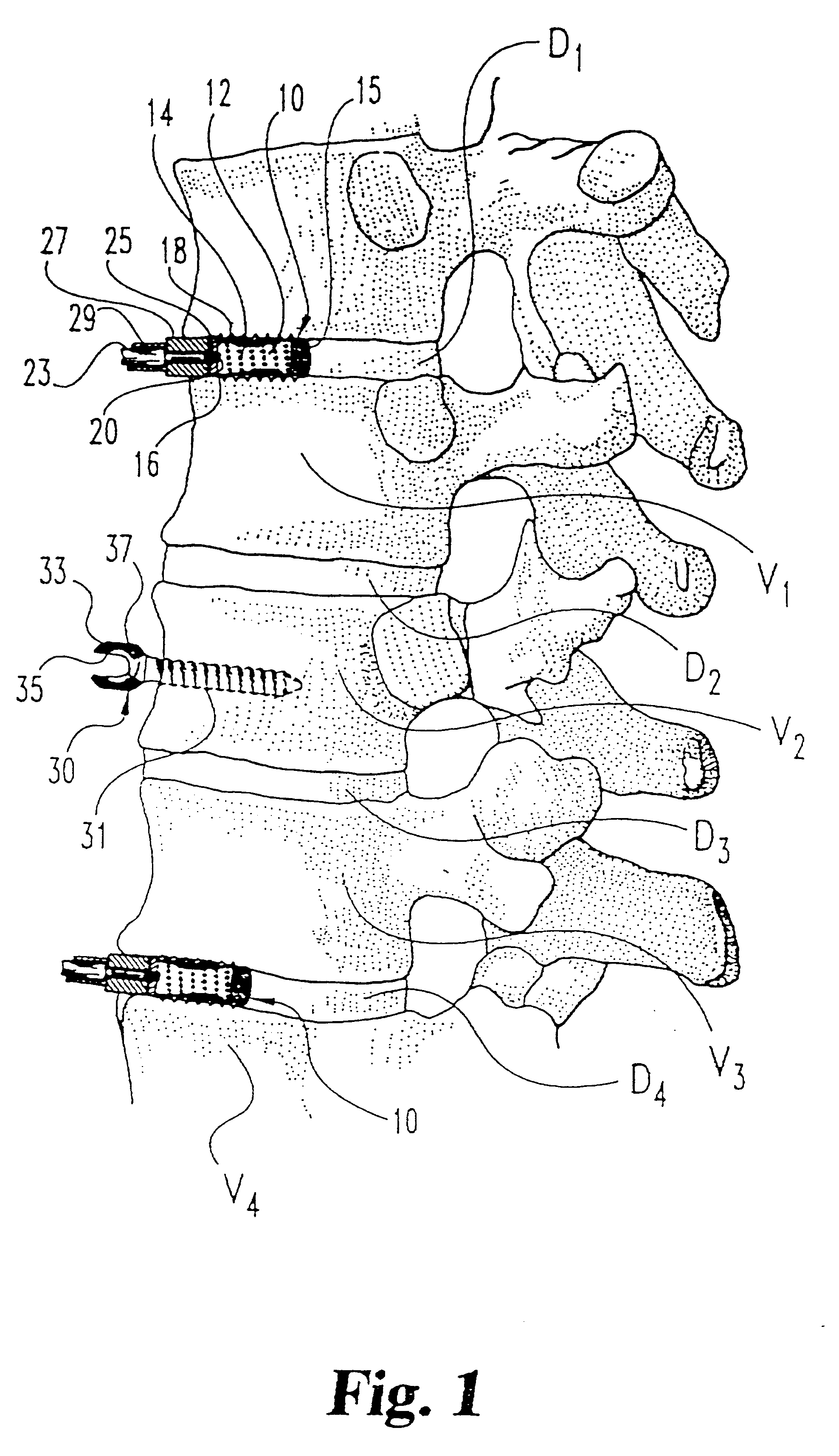
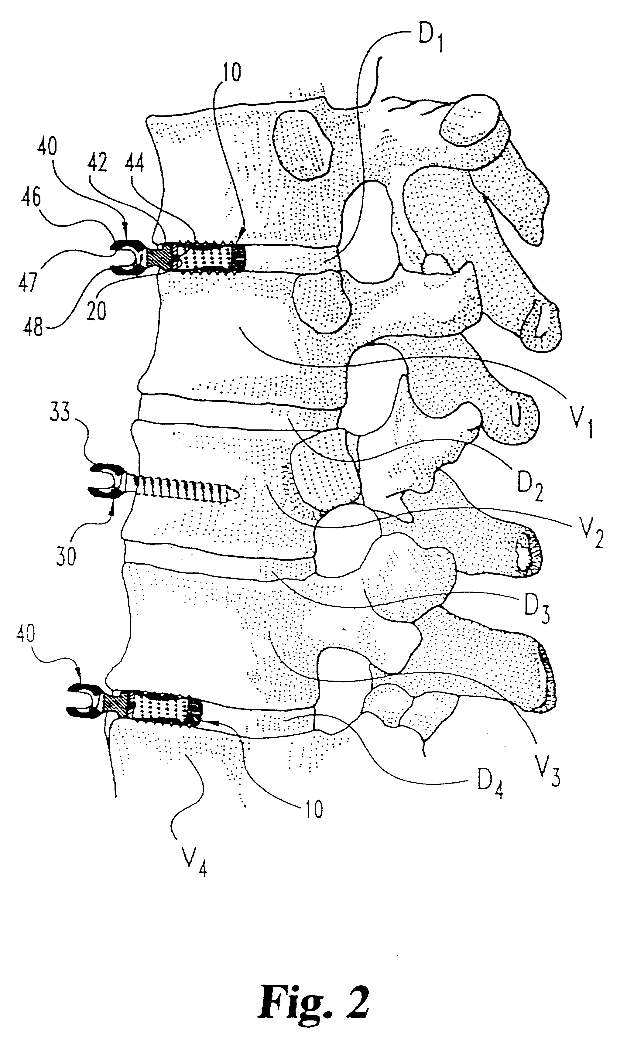
Referring now to FIG. 1, initial steps of the surgical technique contemplated by the present invention are illustrated. In particular, the invention contemplates anterior fixation of several vertebral segments, identified as vertebra vertebrae V.sub.1 -V.sub.4 and their adjacent discs D.sub.1 -D.sub.4. This anterior instrumentation could be used, for instance, to correct a lumbar scoliosis condition followed by fusio...


PUM


Abstract

A system and method for anterior fixation of the spine utilizes a cylindrical implant engaged in the intradiscal space at the cephalad and caudal ends of the construct. The implants are cylindrical fusion devices (10) filled with bone material to promote bone ingrowth and fusion of the disc space. An attachment member (40) is connected to each of the fusion devices (10) and bone screws (30) having similar attachment members (33) are engaged in the vertebral bodies of the intermediate vertebrae. A spinal rod (50) is connected to each of the attachment members using an eyebolt assembly (53, 54, 55). In a further inventive method, a revision of the construct is achieved by removing the fusion devices. Each fusion device is engaged by an elongated guide member (62) over which a cylindrical trephine (70) is advanced. The trephine (70) has an inner diameter larger than the diameter of the fusion implant and includes cutting teeth (72) for extracting a core (84) of bone material around the fusion implant. The trephine (70) and guide member (62) are removed along with the bone core (84) containing the fusion implant (10). The trephine (70) is also used to extract a bone dowel from a solid bone mass to be inserted into the space left by the removed bone core (84).

Description

BACKGROUND OF THE INVENTIONThe present invention concerns a spinal instrumentation system utilizing elongated members extending along the length of the spine and attached to multiple vertebrae by fixation elements, such as bone screws. In particular, the invention concerns anterior instrumentation, together with a surgical technique for implanting the instrumentation. The invention also contemplates a surgical revision technique for this spinal instrumentation.Historically, correction of spinal disorders and treatment of spinal injuries was approached posteriorly, or namely from the back of the patient. Initially, the anterior approach to spinal instrumentation, that is from the front and side of the patient, was not favored, due to the unfamiliarity of this approach to spinal surgeons and due to the fear of severe complications, such as neurovascular injury or compromise of the spinal cord. However, in the face of some reported difficulties in addressing correction of thoracolumbar...

Claims


Application Information

Patent Timeline
Patent Type & Authority Patents(United States)
IPC IPC(8): A61B17/16A61B17/70A61B17/58A61F2/00A61F2/28A61F2/30A61F2/44A61F2/46
CPCA61B17/1637A61B17/1671A61B17/7011A61B17/7032A61B17/7041A61F2/442A61F2/4455A61F2/446A61F2/4611A61F2002/2835A61F2002/30224A61F2002/30235A61F2002/30785A61F2002/30787A61F2002/30797A61F2002/3085A61F2002/448A61F2002/449A61F2002/4619A61F2002/4627A61F2002/4681A61F2230/0069A61F2002/30593
Inventor MICHELSON, GARY K.BOYD, LAWRENCE M.
Owner MICHELSON GARY K
Why Eureka
Try Eureka