Axially compact direct drive for storage disk hub

Inactive Publication Date: 2001-11-27
PAPST MOTOREN GMBH & CO KG
View PDF20 Cites 3 Cited by
  • Summary
  • Abstract
  • Description
  • Claims
  • Application Information

AI Technical Summary

Problems solved by technology

In arrangements of this kind, as a result of the extreme accuracy required as a result of the increasingly small size of the storage disks of 2.5 to 1.8 or even 1.3 inc

Method used


Image

  • Axially compact direct drive for storage disk hub
  • Axially compact direct drive for storage disk hub
  • Axially compact direct drive for storage disk hub

Examples


Example

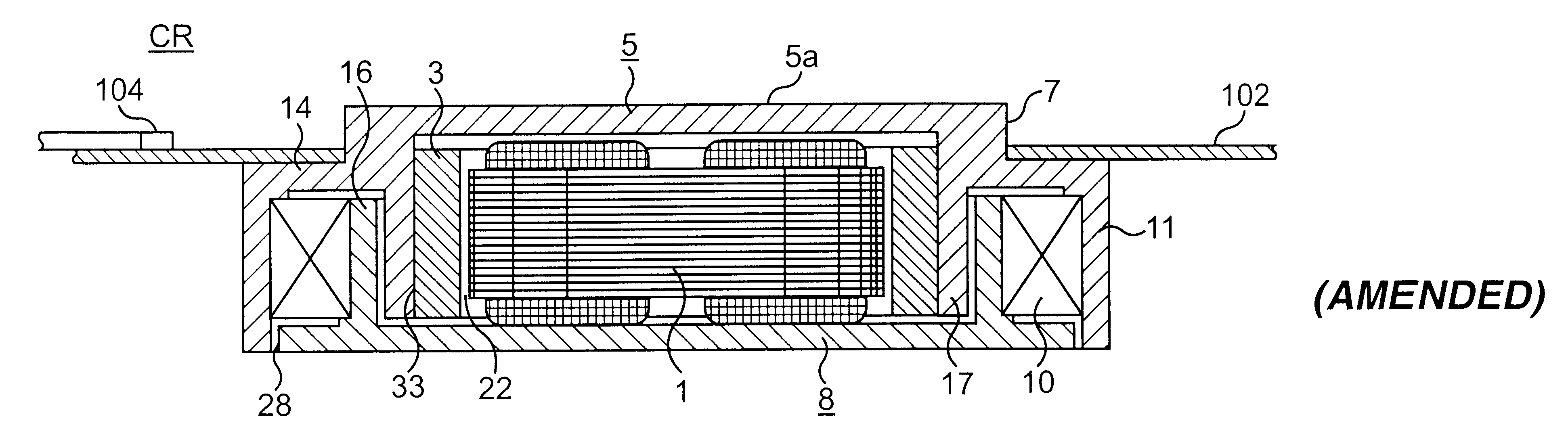
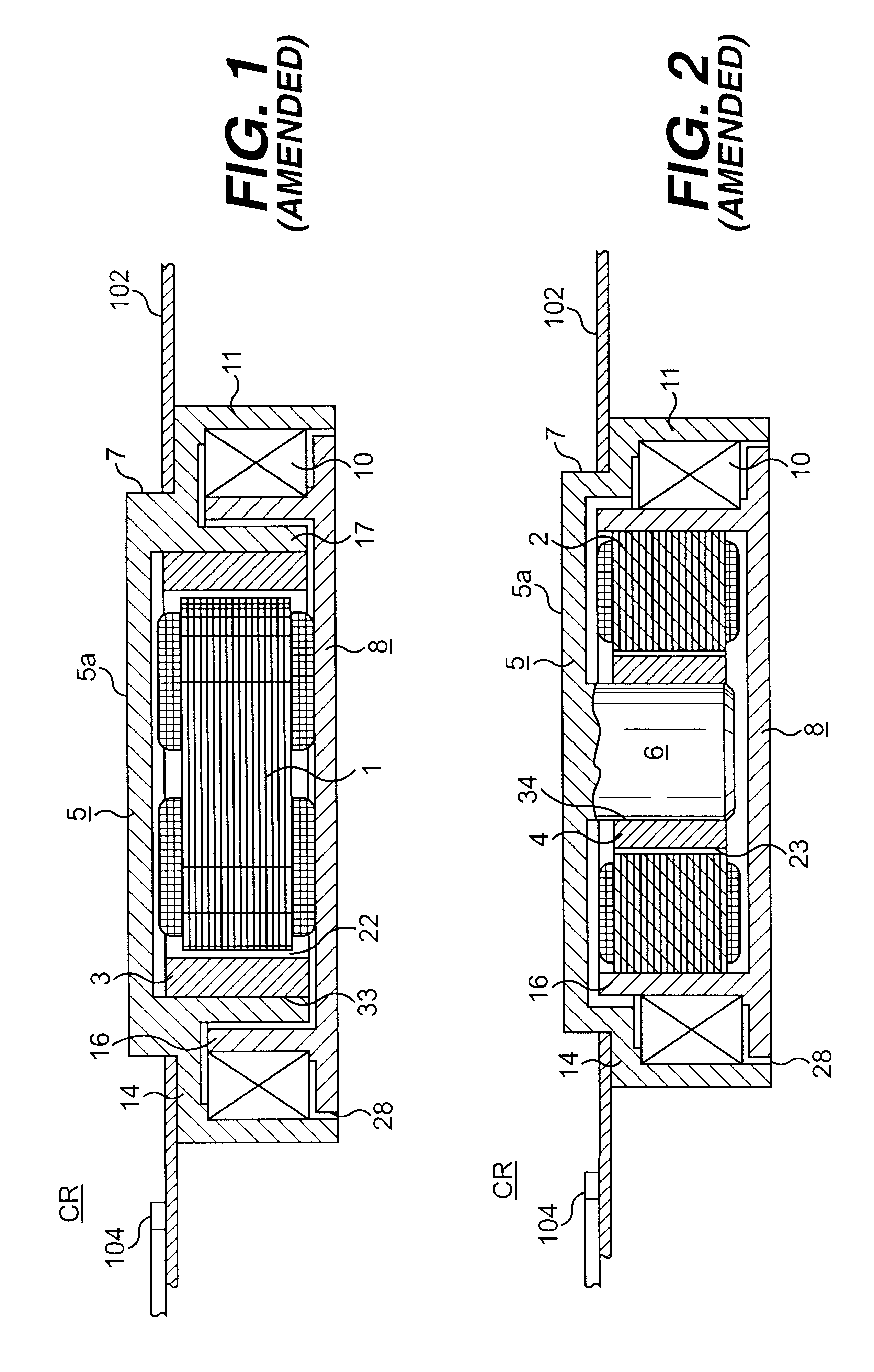
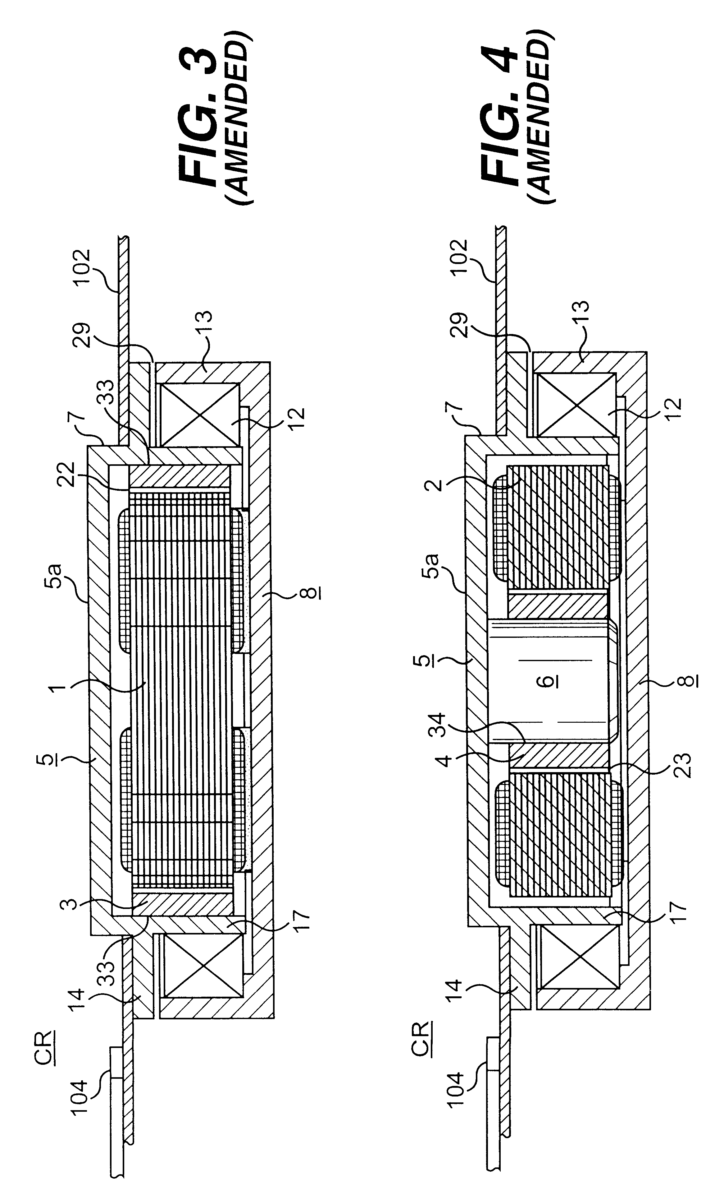
FIGS. 1, 3 and 5 show what are referred to as external rotor variants, in which therefore an internal stator 1 with a cylindrical external circumference is rigidly fixed to a base plate 8, and a permanent magnetic ring 3 is rotatable about the cylindrical external circumference of the internal stator 1. The magnetic ring, with or without a separate hollow cylindrical magnetic return ring 11, forms the electromotive drive element in the external rotor, which is in the shape of a cup or a bell and into which this permanent magnetic rings is inserted.

FIGS. 2, 4 and 6 show as an alternative what are referred to as internal rotor solutions, in which a rotor shaft 6 directly carries a permanent magnetic rotor ring (if necessary, also with the interposition of a soft magnetic, hollow cylindrical return ring), the external circumference of which rotates in the interior of a hollow annular stator iron core which is in turn rigidly connected to a base plate 8.

The rotor may advantageously comp...


PUM


Abstract

An axial compact direct drive for a storage disk comprises a stator, a rotor carrying a hub for receiving storage disks and a bearing arrangement. The bearing arrangement is disposed at a radially external edge of the hub to rotatably support the hub against axial and radial movement. The rotor is electrically driven at locations in the center of the stator or at locations surrounding the stator.

Description

BACKGROUND OF THE INVENTIONThe application relates to a storage disk direct drive including a motor and a bearing arrangement for rotatably supporting a hub that carries storage disks. In arrangements of this kind, as a result of the extreme accuracy required as a result of the increasingly small size of the storage disks of 2.5 to 1.8 or even 1.3 inches in diameter (1 inch=25.4 mm), it is difficult to observe the extreme tolerances and to meet the specific quality requirements which must be achieved in these motors. These requirements of errors relate to non-repeatable run out or NRR. In addition, the influence of temperature deviations must be compensated for. Furthermore, a specific load-carrying capacity must be guaranteed for the bearing arrangement and certain resonance frequencies must be avoided.Therefore, the object of the invention is to design a massproducible subminiature motor by means of which the abovementioned properties are additionally obtained.BRIEF DESCRIPTION OF...

Claims


Application Information

Patent Timeline
IPC IPC(8): G11B19/20G11B25/04H02K7/08G11B33/14H02K5/10H02K5/173
CPCG11B19/2009G11B25/043G11B33/1473H02K5/10H02K5/173H02K7/088
Inventor MULLER, UWEHERMANN, MICHAEL
Owner PAPST MOTOREN GMBH & CO KG
Why Eureka
Try Eureka