Power operated tape measure

a tape measure and power technology, applied in the direction of measuring tapes, measuring devices, instruments, etc., to achieve the effect of smooth extension of tapes and convenient operation

Inactive Publication Date: 2002-09-03
PULLEN SCOTT
View PDF16 Cites 20 Cited by
  • Summary
  • Abstract
  • Description
  • Claims
  • Application Information

AI Technical Summary

Benefits of technology

Accordingly it is the primary object of the present invention to provide a power-driven tape measure which can smoothly extend the tape as desired.
It is another object of the present invention to provide a power operated tape measurement which can retract the tape into its housing.
It is still another object of the present invention to provide a power operated tape measure which is easy to operate with one hand.

Problems solved by technology

The primary drawback with this type of device is that it requires that both hands of the operator in use in order to extend the tape with one hand holding the housing and the other hand extending the tape from its coiled position within the housing.

Method used


Image

  • Power operated tape measure
  • Power operated tape measure
  • Power operated tape measure

Examples


Embodiment Construction

For the purpose of promoting and understanding of the principles of this invention, reference will now be made to the embodiment illustrated in the drawings. Specific language will be used to describe the invention, however, it must be understood that no limitation of the scope of the invention is thereby intended, such alterations and further modifications in the illustrated device, and such further applications of the principles of the inventions as illustrated herein being contemplated as would normally occur to one skilled in the art to which the invention relates.

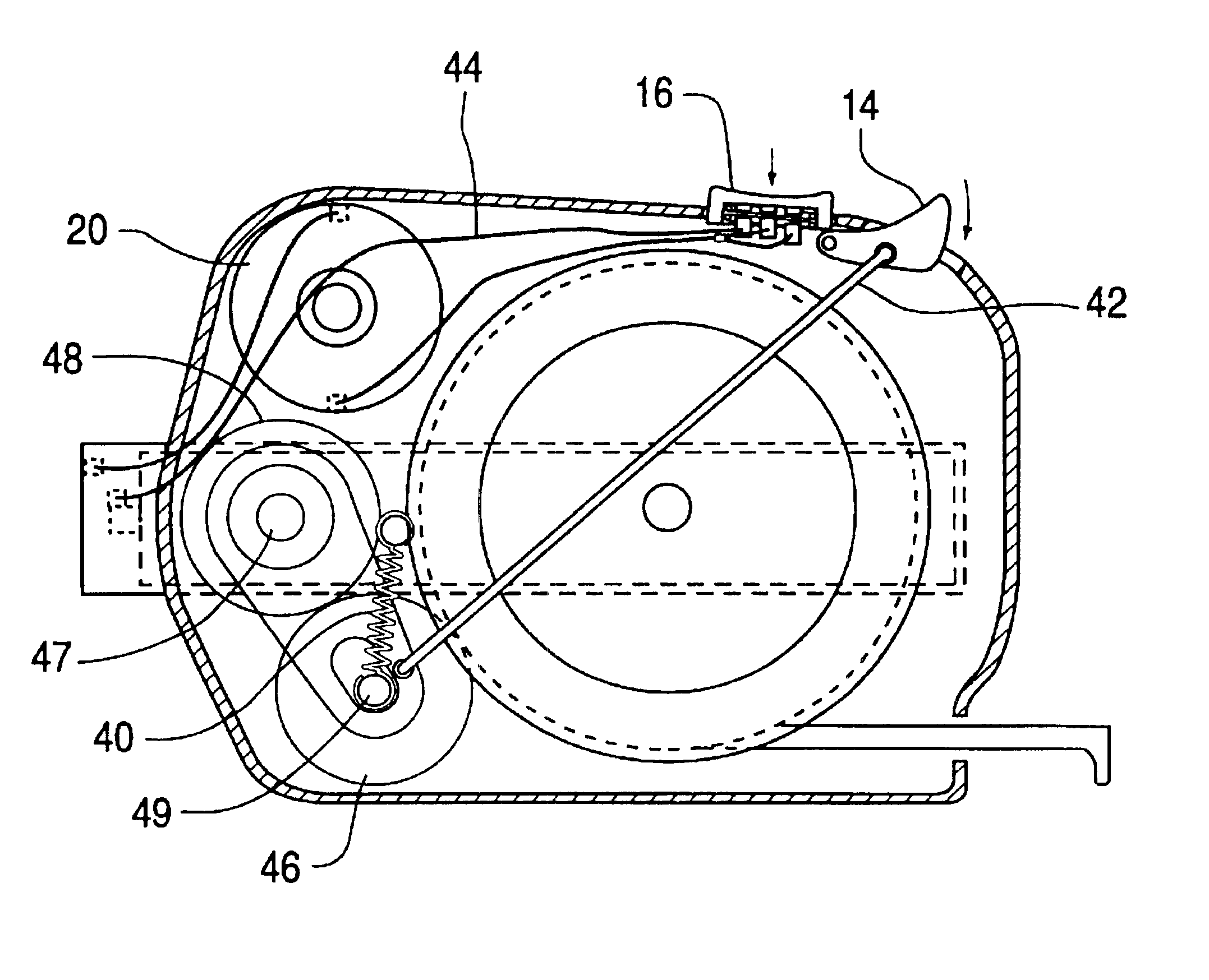
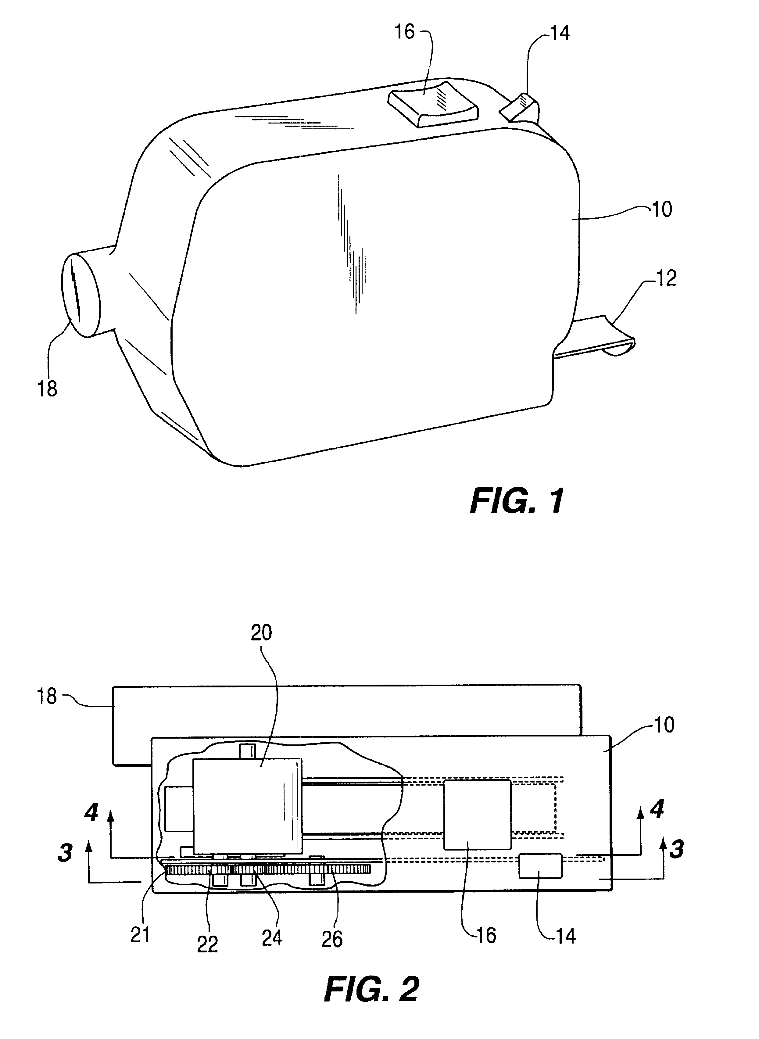
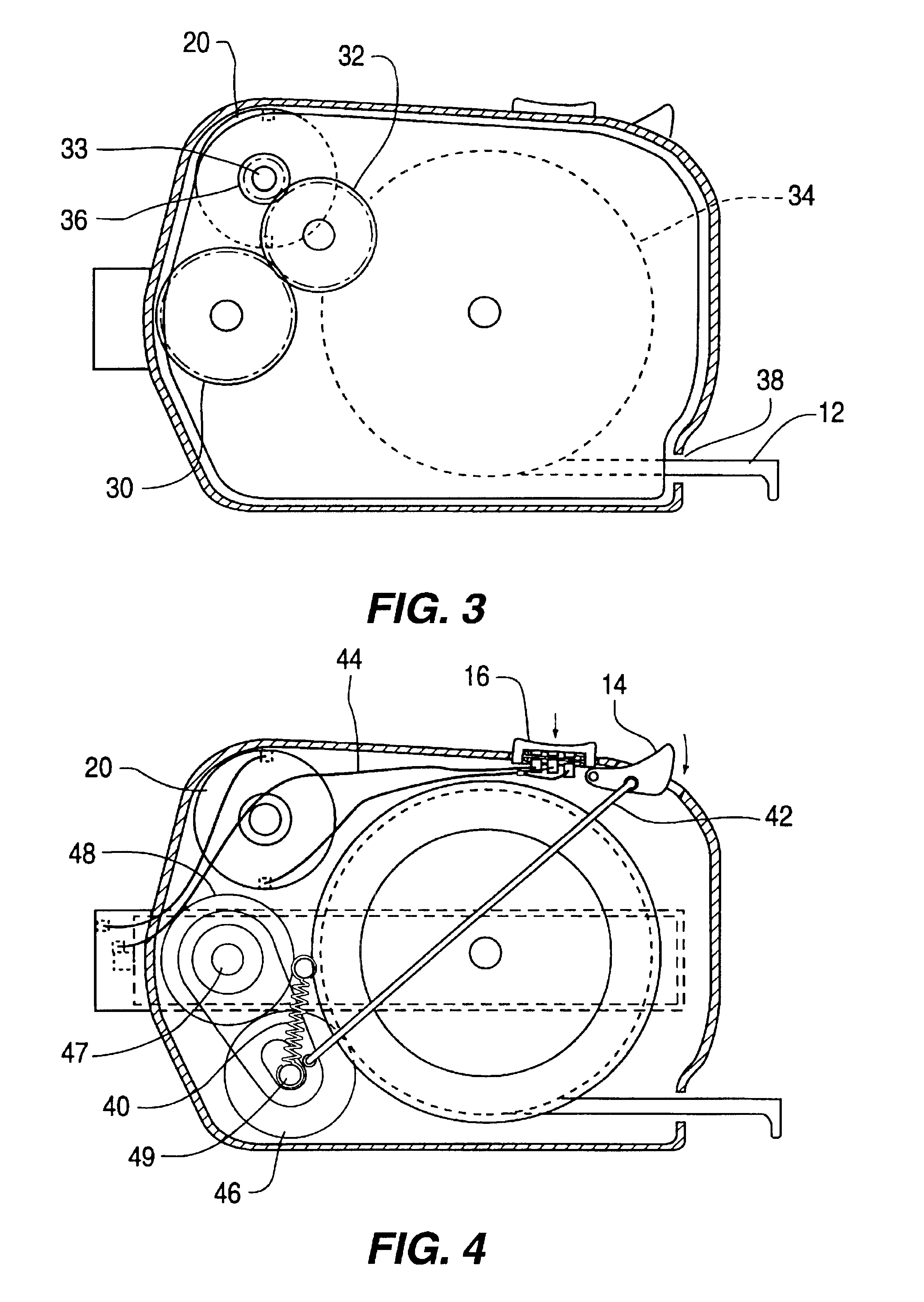
With reference to the drawings, and in particular to FIGS. 1, 2, 3, & 4 thereof, the power-operated tape measure according to the present invention comprises a case 10 on which are mounted switches 14 and 16. The case 10 is formed with a chamber 18 for receiving batteries (not shown) and an outlet 38 for the passage of a tape 12. An annular reel 34, is rotatably arranged within the case 10. Motor 20, is fixedly mounted...


PUM


Abstract

A hand-held measuring device including a case and flexible steel spring-biased measuring tape wound about an annular reel fitted within a circular housing within the case, a single battery-powered motor having an output shaft, a driving wheel fixedly mounted on the output shaft of the motor for directly engaging the surface of the tape and thereby pushing the tape out of the case, a first switch mounted on the case for controlling the motor, a pull rod connected to the drive wheel, and a second switch mounted on the case and connected to the pull rod for disengaging the driving wheel from the tape surface.

Description

FIELD OF THE INVENTIONThis invention relates to a hand-held measuring device directed to a motorized tape measure.BACKGROUND OF THE INVENTIONVarious forms of measuring devices have been in use for years with the two most common devices being the folding measurer ruler commonly used by carpenters and the convenient hand-held tape measure.One of the attributes of the hand-held tape measure is that it is lightweight and easily stored and used; the tape is compactly coiled within the housing and is spring-biased to retract into the housing when not in use. This device provides an additional feature in that the tape as it is extended has a slightly concave section which allows the tape to extend outwardly in a self-supporting configuration for a substantial distance.The primary drawback with this type of device is that it requires that both hands of the operator in use in order to extend the tape with one hand holding the housing and the other hand extending the tape from its coiled posi...

Claims


Application Information

Patent Timeline
Patent Type & Authority Patents(United States)
IPC IPC(8): B65H75/40B65H75/38G01B3/10G01B3/02B65H75/44
CPCG01B3/1005G01B2003/1017G01B2003/1028G01B2003/103G01B2003/1035G01B2003/1038G01B3/1046
Inventor PULLEN, SCOTT
Owner PULLEN SCOTT
Why Eureka
Try Eureka