Lockable quick release apparatus

a quick release and lockable technology, applied in the direction of release mechanisms, anti-theft cycle devices, cycle equipments, etc., can solve the problems of easy defeat, complex mechanisms, easy to be stolen, etc., and achieve the effect of preventing the misposition of the fork of the bicycl

Inactive Publication Date: 2003-04-29
BUCHALTER CHARLES P
View PDF27 Cites 16 Cited by
  • Summary
  • Abstract
  • Description
  • Claims
  • Application Information

AI Technical Summary

Benefits of technology

The forgoing and other deficiencies of the prior art are addressed by the present invention which is directed to a lockable quick release mechanism which is simple to attach and remove, makes theft extremely difficult, and is inexpensive.
Another object of the present invention is to provide a quick release locking apparatus which prevents mis-positioning of a bicycle fork.

Problems solved by technology

A major drawback to such quick release mechanisms is that they make the bicycle and / or the wheel an easy target for theft.
In particular, the mechanisms are either complex, and therefore expensive, or are easily defeated.
Furthermore, if the locking mechanism is too complicated and difficult to utilize, it will defeat the original purpose for the quick release mechanism, namely, the ability to rapidly assemble and disassemble the respective parts.
The Davidson device, however, requires significant extra hardware, and is therefore more expensive and difficult to operate.
Furthermore it is less versatile in that it can not be used with a conventional padlock.
This device is also much more complex and employs an integral lock along with an intricate securing mechanism.

Method used


Image

  • Lockable quick release apparatus
  • Lockable quick release apparatus
  • Lockable quick release apparatus

Examples


Embodiment Construction

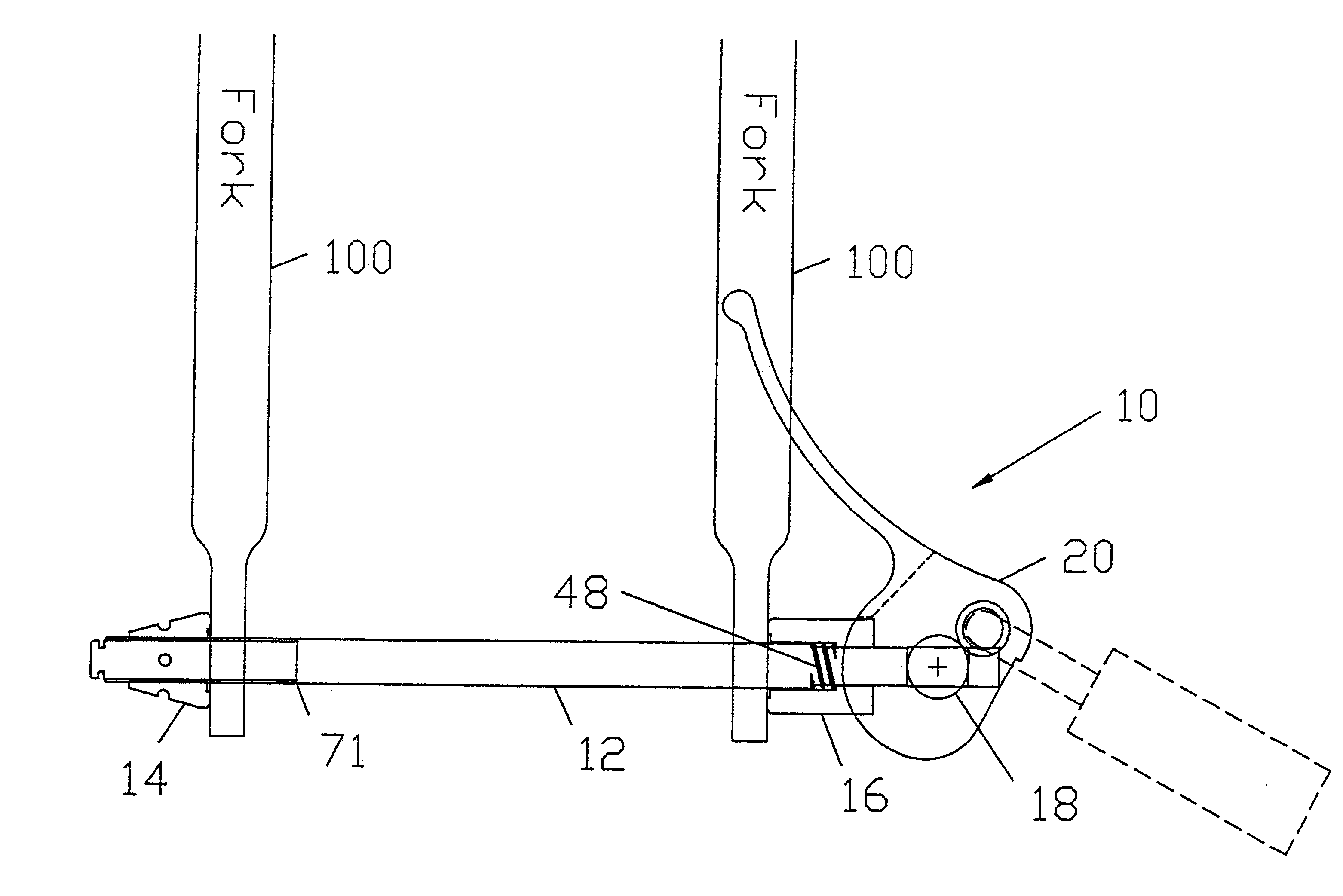
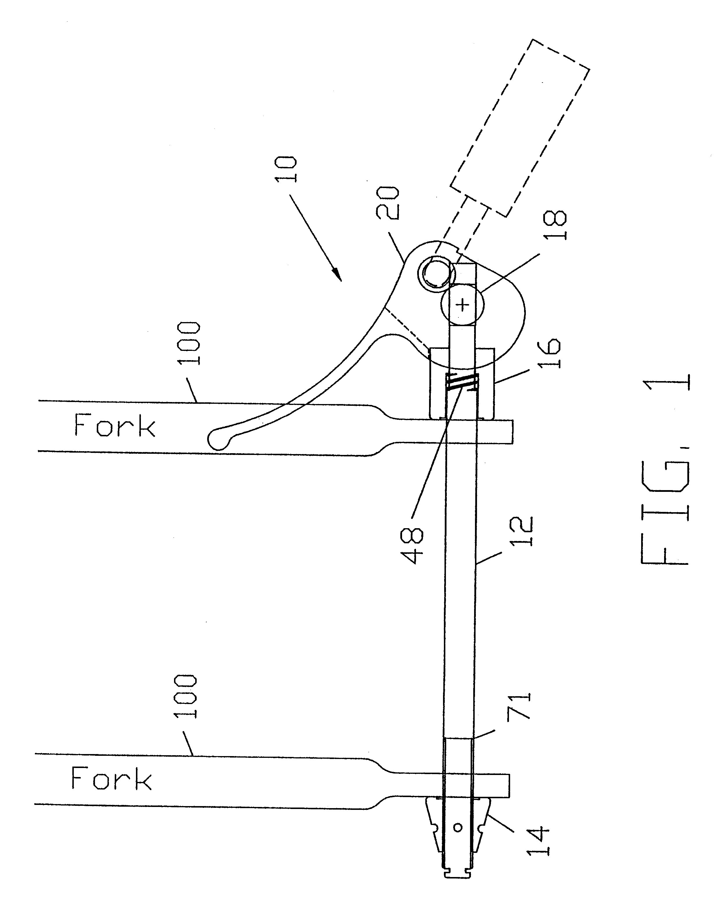
Referring to FIG. 1, the quick release apparatus 10 according to the present invention is shown in cross-section. The quick release apparatus 10 includes a shaft 12, an adjuster nut 14, a cam follower 16, a barrel nut 18 and a cam lever 20. The quick release apparatus 10 is shown engaged with the blades 100 of a bicycle fork.

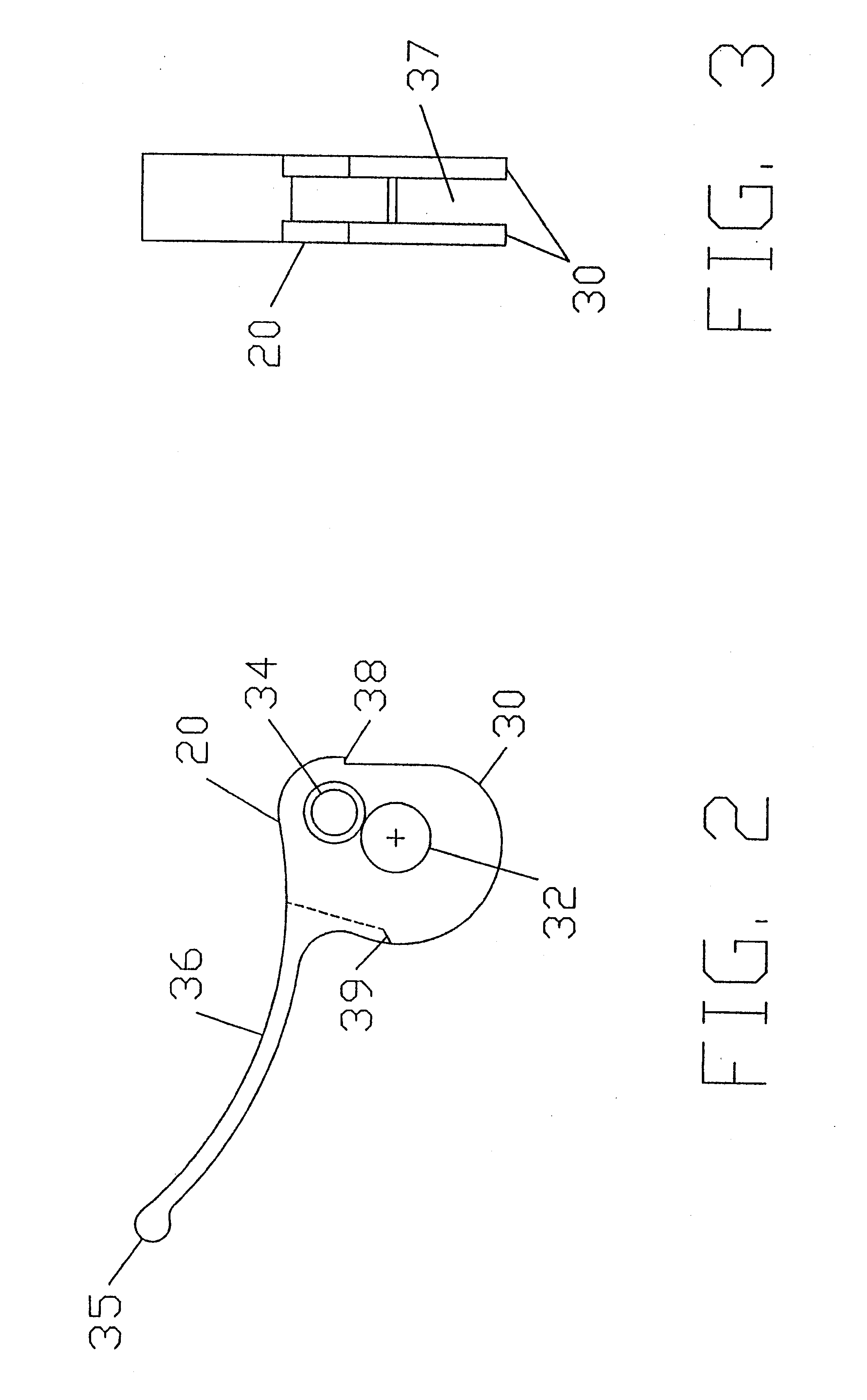
By far the most complex part of the quick release apparatus 10 is the cam lever 20, which is shown in greater detail in FIGS. 2 and 3. The cam lever 20 has a camming surface 30, a pivot hole 32 which accommodates the barrel nut 18, a lock hole 34 for accommodating a padlock (not shown), a handle 36, cam stops 38 and 39, and finger grip 35. Referring to FIG. 3, it can be seen that the quick release apparatus 10 has a groove or slot 37.

The cam follower 16 is shown in FIGS. 4a-e. The cam follower 16 is substantially cylindrical. Referring to end view 4a, the cam follower 16 has a through hole 40 formed concentrically in the cam follower 16. A pair of anti-rotation ...


PUM


Abstract

A lockable quick release mechanism is provided having a cam lever threaded onto a shaft which extends through and beyond a barrel nut, fitted in the cam lever so that it will provide interference with a padlock when locked. The cam lever has a lock hole for the padlock, and a curvature which, when locked, will stop the cam lever from being rotated more than a few degrees due to interference with the fork blade. A cam follower is provided on the shaft and has anti-rotation tabs, which fit into the clevis of the cam lever, and which engages the camming surface of the cam lever thereby preventing the cam lever from being rotated in the locked position due to the amount of friction between the cam follower and the fork tip. The cam follower is always biased by a spring against the camming surface to prevent a fork blade from being mis-positioned between the cam follower and the camming surface.

Description

BACKGROUND OF THE INVENTION1. Field of the InventionThe present invention relates to a quick release apparatus. More particularly, the present invention relates to a quick release apparatus to which a lock, such as a conventional padlock can be attached to prevent an item, such as a bicycle fork or bicycle seat post, from being disengaged.2. Description of the Prior ArtQuick release mechanisms have become prevalent for use in securing bicycle wheels in place, and are finding increasing use in releasably securing seats to bicycle frames. Such quick release mechanisms typically have a hollow shaft, a skewer extending through the shaft, a nut on one end of the skewer, and a lever arm on the opposite end of the skewer. The lever arm can be pivoted to tighten or loosen the mechanism. For a bicycle wheel, the lever has a camming surface so that, as the lever is pivoted, the camming surface engages or disengages the adjacent fork blade.A major drawback to such quick release mechanisms is t...

Claims


Application Information

Patent Timeline
Patent Type & Authority Patents(United States)
IPC IPC(8): B62K25/00B62H5/00B62K25/02
CPCB62H5/001B62K25/02B62K2206/00Y10S403/04Y10T70/5872
Inventor BUCHALTER, CHARLES P.
Owner BUCHALTER CHARLES P
Why Eureka
Try Eureka