Protective component for power cable of an industrial electro-magnetic lifting device

a protection component and lifting device technology, applied in the direction of adjustment joints, pipe joints, electrical equipment, etc., can solve the problems of power cable that extends from the crane to the lifting magnet being very susceptible to physical damage, power cable can potentially be cut and/or severed, pinched, compressed, etc., and achieves the effect of simple manufacturing

Active Publication Date: 2018-07-24
WINKLE IND INC
View PDF15 Cites 3 Cited by
  • Summary
  • Abstract
  • Description
  • Claims
  • Application Information

AI Technical Summary

Benefits of technology

[0008]An objective of the present invention is to provide a protective component for a power cable of an industrial electro-magnetic lifting device that is simple to manufacture.
[0009]Another objective of the present invention is to provide a protective component for a power cable of an industrial electro-magnetic lifting device that is simple to assemble or attach to the power cable.
[0010]Yet another objective of the present invention is to provide a protective component for a power cable of an industrial electro-magnetic lifting device that shields the power cable from physical damage during operation of the electro-magnetic lifting device, while allowing the cable to remain flexible.

Problems solved by technology

The power cable that extends from the crane to the lifting magnet is very susceptible to physical damage during operation.
More specifically, during operation of the crane and attached lifting magnet, the power cable can potentially become cut and / or severed, pinched, smashed, compressed, or otherwise physically damaged.
Such physical damage imparted to the power cable can in turn potentially damage the power cable, lifting magnet and / or power source components on the crane, leading to safety and reliability concerns, as well as increased maintenance and repair costs.

Method used


Image

  • Protective component for power cable of an industrial electro-magnetic lifting device
  • Protective component for power cable of an industrial electro-magnetic lifting device
  • Protective component for power cable of an industrial electro-magnetic lifting device

Examples


Embodiment Construction

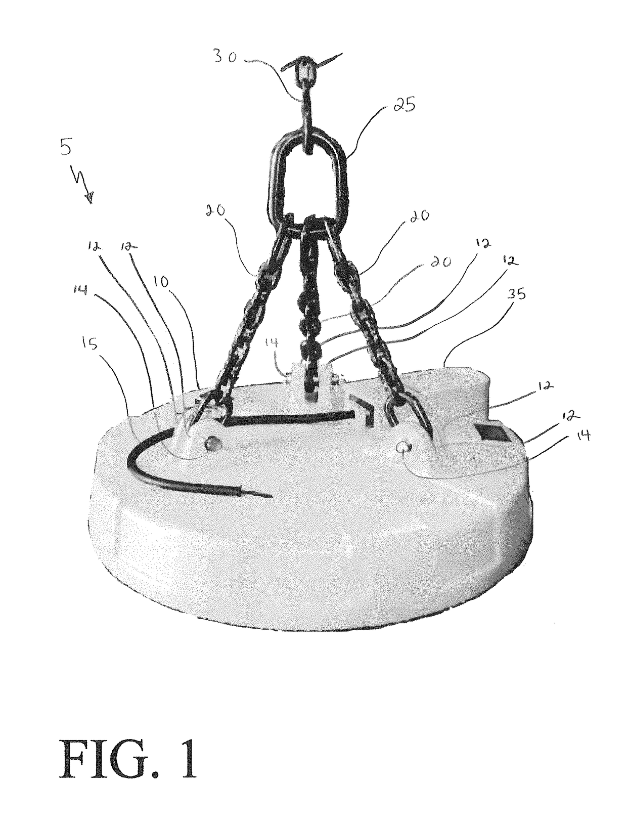
[0026]In order to better understand the protective component of the present invention and the environment in which it operates, a prior art lifting magnet for an industrial electro-magnet lifting device is shown in FIG. 1 and is indicated generally at 5. Lifting magnet 5 is an electro-magnet capable of producing a magnetic field for lifting ferrous metal objects upon introduction of electricity to a plurality of electro-magnetic field inducing components (not shown) of the lifting magnet. Industrial electro-magnet 5 includes a casing 10, which houses the electro-magnetic field inducing components of the lifting magnet. Casing 10 is formed with three pairs of lugs 12 for attaching lifting magnet 5 to a crane (not shown). More specifically, lifting magnet 5 includes a plurality of lifting chains 20. Each lifting chain 20 is attached to a respective pair of lugs 12 by a pin 14 disposed through the lifting chain and a horizontally aligned opening (not shown) foliated in each of the resp...


PUM


Abstract

A protective component for a power cable of an industrial electro-magnetic lifting device includes a top portion and a bottom portion. The protective component is formed with an opening, which extends through the top and bottom portion to enable the protective component to be disposed around a power cable of a lifting magnet. The bottom portion includes an inner diameter, which enables the top portion of a second subsequent protective component disposed around the power cable to nest or rest within the bottom portion. A plurality of protective components can be disposed around the power cable so that each protective component bottom opening mates with the top portion of a preceding protective component and the top portion mates with the bottom opening of a subsequent protective component to protect the power cable.

Description

CROSS-REFERENCE TO RELATED APPLICATION[0001]This application claims the benefit of U.S. Provisional Patent Application Ser. No. 62 / 257,374, filed Nov. 19, 2015.BACKGROUND OF THE INVENTION[0002]Technical Field[0003]The present invention relates generally to the art of below-the-hook electro-magnetic lifting devices. More particularly the invention is directed to a protective component for a power cable of an industrial electro-magnetic lifting device. More specifically, the present invention is directed to a protective component that is disposed around and along a desired length of the power cable on a lifting magnet to protect the power cable from being damaged during operation of the lifting device. The protective component is easy to manufacture and assemble onto the power cable and substantially eliminates the potential of the power cable becoming pinched, cut and / or severed, smashed or otherwise physically damaged during operation of the electro-magnetic lifting device.[0004]Bac...

Claims


Application Information

Patent Timeline
Patent Type & Authority Patents(United States)
IPC IPC(8): F16L27/02H02G3/04H02G3/02
CPCH02G3/0475H02G3/02F16L27/02
Inventor SCHATZ, JOSEPH T.
Owner WINKLE IND INC
Why Eureka
Try Eureka