Metal shingle with gutter and interlocking edges

a technology of metal shingles and gutters, applied in the field of roof shingles, can solve the problems of water migrating around the edges of metal shingles, or smooth surface, shingle,

Inactive Publication Date: 2003-08-12
VAIL METAL SYST
View PDF14 Cites 47 Cited by
  • Summary
  • Abstract
  • Description
  • Claims
  • Application Information

AI Technical Summary

Benefits of technology

The top edge of the shingle is folded-over toward the top surface of the shingle for engagement with the folded-under lower edge of the next higher shingle on the roof. The folded-over top edge extends all the way to the right edge of the shingle so that it slides under the left edge of the folded-over top edge of the next adjacent shingle to the right side. The folded-under lower edge extends along the lower edge of the shingle but preferably leaves a gap relative to the folded-under lower edge of the next adjacent side shingle. In this way, water is restrained from migrating over the top edge of the shingle and is allowed to flow out the gap between respective folded-under lower edges of the adjacent shingles.

Problems solved by technology

A problem with the prior art interlocking-edge shingle design is that water tends to migrate around the edges of a metal, or smooth surface, shingle.
This problem is particularly prevalent at the corners of the shingle where the folded edges may leave a gap close to the surface of the shingle.

Method used


Image

  • Metal shingle with gutter and interlocking edges
  • Metal shingle with gutter and interlocking edges
  • Metal shingle with gutter and interlocking edges

Examples


Embodiment Construction

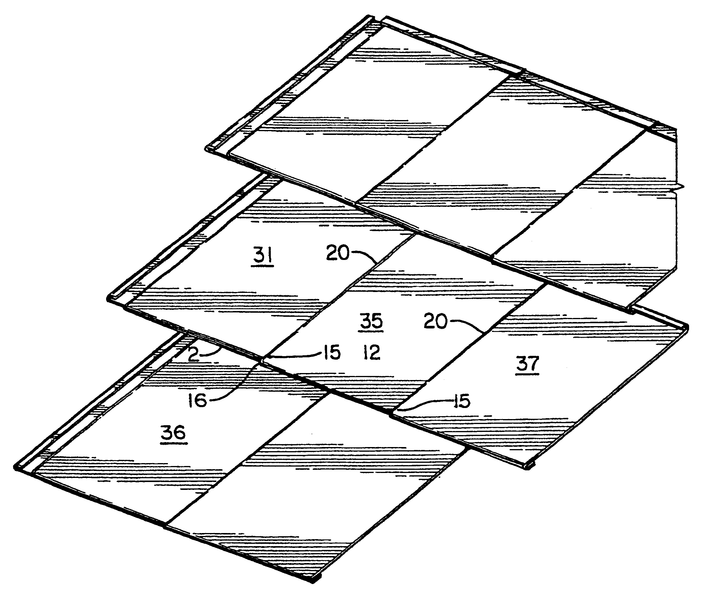
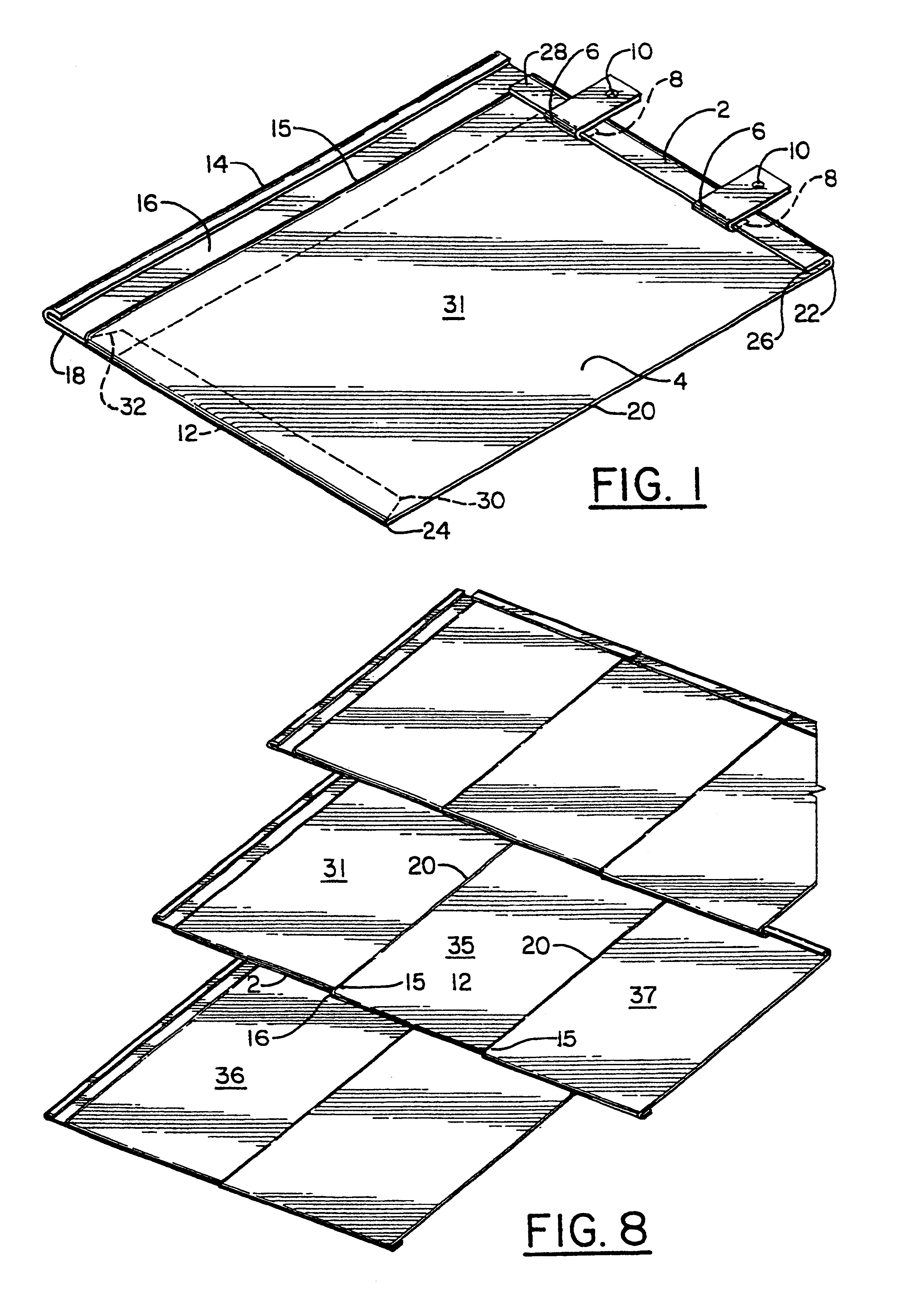
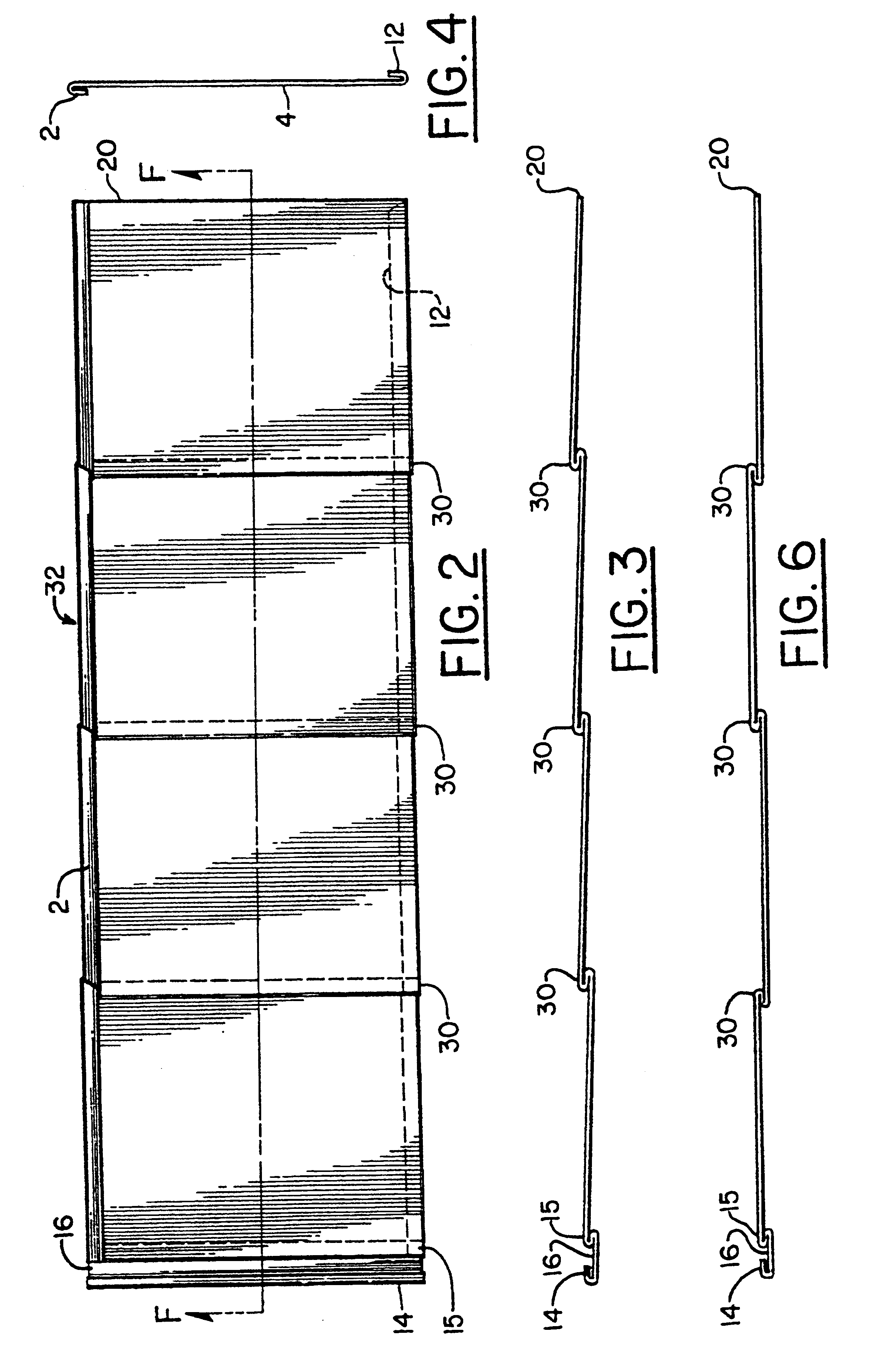
FIG. 1 shows a top view of a preferred embodiment of the shingle 31. Upper edge 2 is folded-over to the top plan surface 4 to allow engagement with mounting bracket 6, or with the lower edge 12 of the next higher shingle. Mounting bracket 6 has a folded-under lower edge 8 and a hole 10. The bracket lower edge 8 is hooked onto the shingle upper edge 2 and nailed to the roof (not shown) through hole 10 to hold the shingle 31 in place on the roof (not shown).

The shingle lower edge 12 is folded under for engagement with the upper edge fold 2 of the next lower shingle. The left side, or trailing, edge 14 is folded-over toward the top surface of the shingle 31. The shingle top surface has an S fold 15 spaced inwardly from the trailing edge 14 that divides a gutter surface 16 from the rest of the top surface 4 of the shingle 31. Thus, water flowing to the left side of the shingle 31 over the S fold 15 is caught in a gutter formed by trailing edge 14, gutter surface 16 and S fold 15. The wa...


PUM


Abstract

A shingle is formed with a first, or trailing, side edge folded over toward the top surface of the shingle to catch moisture and direct it down to the top surface of the next lower shingle. A second, or leading, side edge of the shingle is not folded. An "S" shaped fold, spaced apart from the trailing edge fold, receives the unfolded leading edge of an adjacent shingle. The tailing edge and S fold form a gutter under the leading edge of the adjacent shingle. The top edge of the shingle is folded-over toward the top surface of the shingle for engagement with the folded-under lower edge of the next higher shingle. The folded-over top edge extends to the right or leading edge of the shingle and slides under the left edge of the folded-over top edge of the next adjacent shingle to the fight side. The folded-under lower edge extends along the lower edge of the shingle but leaves a gap relative to the folded-under lower edge of the lateral adjacent shingle. In this way water is caught by the gutter and flows out the gap between folded-under lower edges of laterally adjacent shingles. One or more S-shaped folds are also made in the middle of the shingle to form a panel having the appearance of multiple shingles.

Description

BACKGROUND OF THE INVENTION1. Field of the Invention:This invention relates to roofing shingles and more particularly to a metal shingle having interlocking folding edges designed to prevent moisture from migrating around the edges of the shingle and folds in the middle of the shingle.2. Description of the Prior Art:Metal shingles with interlocking edges are known in the art. U.S. Pat. Nos. Vallee 4,185,436, Vallee 4,218,857, Cosden 3,347,001, Marini et al. 3,269,075, Newlin et al 3,216,741 and Waske 3,209,506 all disclose interlocking edges.A problem with the prior art interlocking-edge shingle design is that water tends to migrate around the edges of a metal, or smooth surface, shingle. This problem is particularly prevalent at the corners of the shingle where the folded edges may leave a gap close to the surface of the shingle. Also, the water tends to migrate around the interlocking folds at the side edges of the shingle.SUMMARY OF THE INVENTIONIt is the object of the present in...

Claims


Application Information

Patent Timeline
Patent Type & Authority Patents(United States)
IPC IPC(8): E04D1/12E04D1/26E04D1/18E04D1/00
CPCE04D1/18E04D1/265E04D2001/305E04D2001/3414
Inventor PLATH, DAVID J.BUSTER, JAMES M.
Owner VAIL METAL SYST
Why Eureka
Try Eureka