Universal coupler for spinal fixation

a universal coupler and spinal technology, applied in the field of spinal fixation connectors, can solve the problems of complex surgical procedures, designed to accommodate stress much higher, and current bolt-to-rod connectors that do not allow adjustment in multiple planes

Inactive Publication Date: 2006-03-21
IBM CORP
View PDF36 Cites 221 Cited by
  • Summary
  • Abstract
  • Description
  • Claims
  • Application Information

AI Technical Summary

Problems solved by technology

However, current bolt to rod connectors do not allow for adjustability in multiple planes in order to better conform to the anatomical structure of the patient and to eliminate initial stresses on the spinal fixation construct.
In spinal surgery that requires distraction, compression, and rotation of the construct to obtain proper assembly, stresses are put on the component parts of existing spinal fixation systems and on the vertebral column, which are not designed to accommodate stresses much higher than those encountered during normal patient activity.
Additionally, some existing fixation systems, such as U.S. Pat. Nos. 5,209,752 and 5,176,697, require lateral or medial approaches to assemble and tighten the construct which causes complicated surgical procedures due to the soft tissues that are lateral to the incision.
Potential damage can also occur to neurological elements that are medial to the construct.
Current spinal fixation systems, for example such as those shown in U.S. Pat. Nos. 4,719,905 and 5,296,014, also have many pieces to assemble and lack anatomical adjustability which results in long surgeries that put increased stresses on the surgeon and surgical staff.
The large number of pieces in current fixation systems require hospitals to keep large inventories which is difficult during the present time of medical cost containment.

Method used


Image

  • Universal coupler for spinal fixation
  • Universal coupler for spinal fixation
  • Universal coupler for spinal fixation

Examples


Embodiment Construction

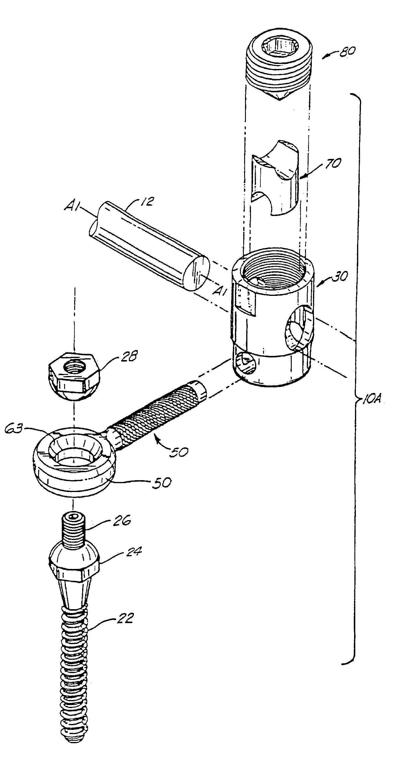
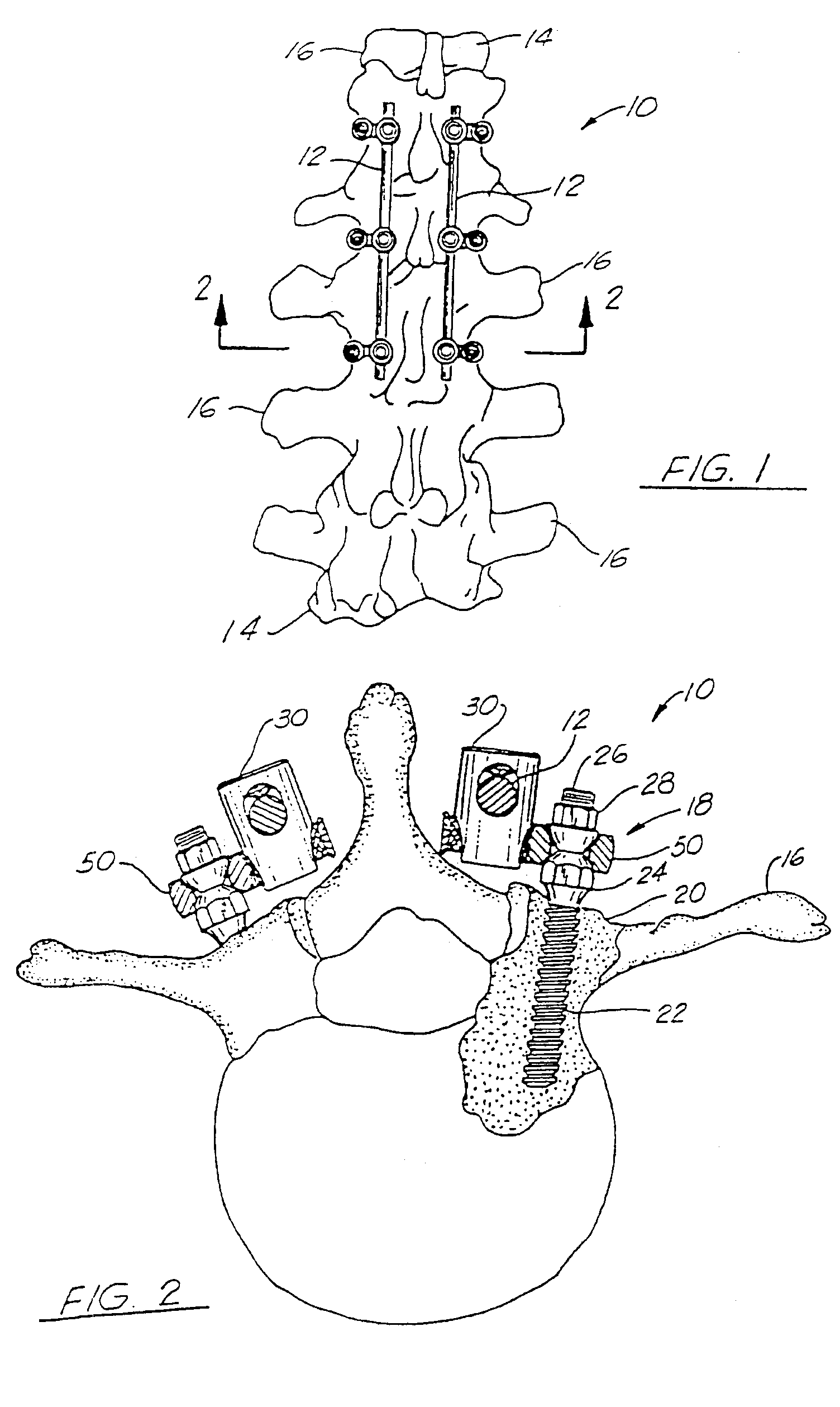
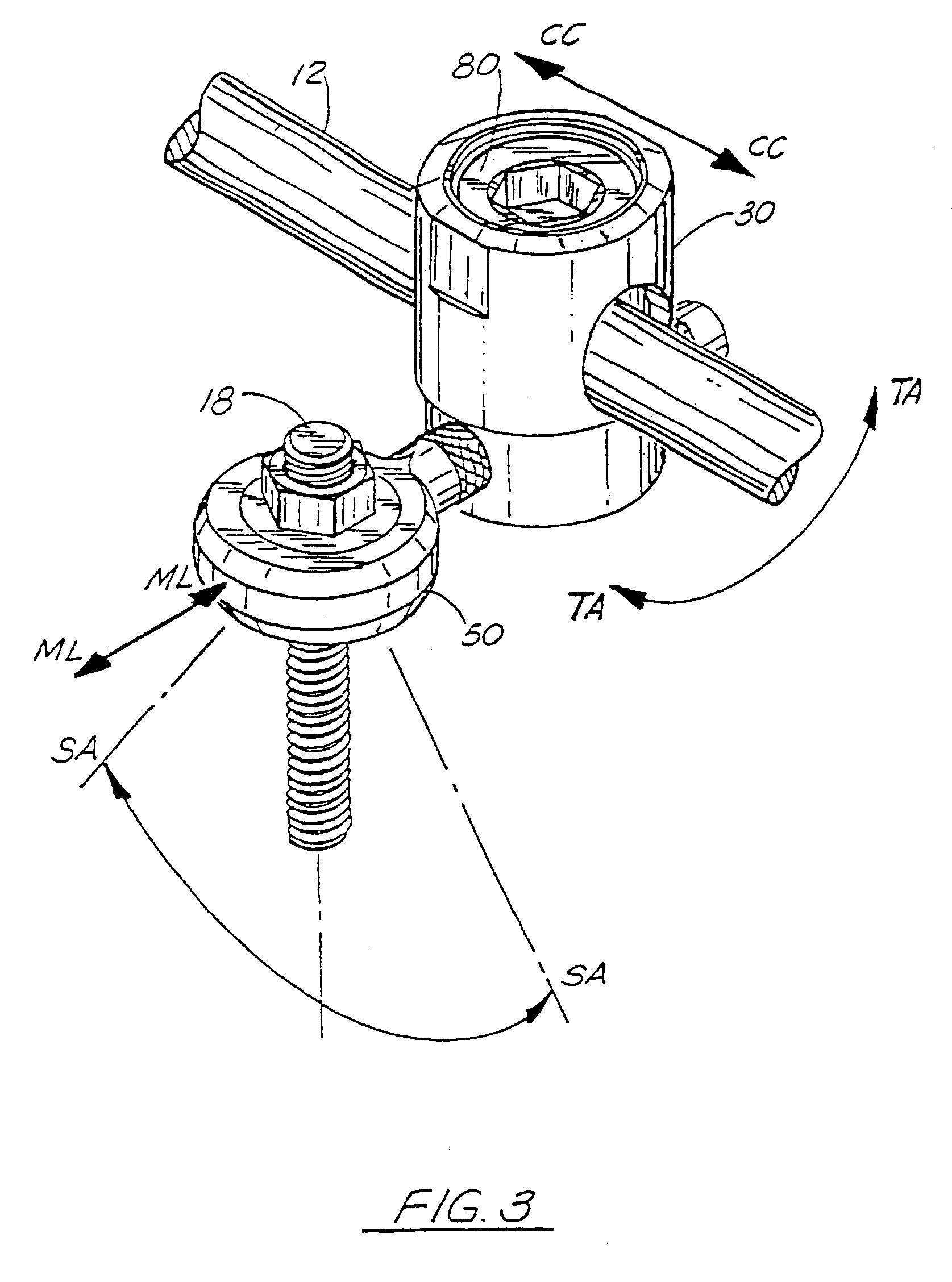
[0034]FIGS. 1 and 2 show the preferred embodiment of the coupler assembly of the present invention, designated generally by the numeral 10 implanted in a spinal column. Coupler assembly 10 includes a coupler body or member 30, an eyebolt member 50, an insert 70 and a set screw 80, and is used to attach longitudinal rods 12 to a vertebral column 14 comprising a plurality of vertebrae 16. The coupler assembly 10 is shown attached to three vertebrae 16 as part of a spinal implant system that is used to hold and stabilize vertebrae 16. Although the attachment of only three vertebrae 16 is shown, it should be understood that the number of assemblies 10 used can vary such that any number of vertebrae can be held in place.

[0035]Each of the assemblies 10 is connected to a respective vertebrae 16 by a fastener 18 which may be either a bone bolt (FIGS. 2, 3, 4) or a bone screw 18A (FIG. 4A). The fastener 18 is shown in FIGS. 2, 3 and 4 as bone bolt 18 having a first threaded end portion 22 fo...


PUM


Abstract

A spinal rod coupler assembly providing four degrees of freedom for connecting a spinal rod to a vertebrae of a patient which includes a tubular coupler member, an eyebolt, an insert and a set screw. The coupler member has a longitudinal bore, a central axis, and an end portion that is open ended and internally threaded and a second end portion that is closed. A plurality of openings in the tubular coupler member that includes a first pair of openings intersecting the central axis of the bore at generally right angles and a second pair of openings intersecting the central axis of the bore at generally right angles. The first and second pairs of openings being perpendicular to each other. The first pair of openings are sized and shaped to receive a spinal rod. The eyebolt has a shank portion and an eye portion, with the shank portion being insertable through the second pair of openings of the coupler body. The eye portion has an opening sized and shaped to mate with a selected bone bolt or bone screw. The insert fits within the bore and has opposed, arc-shaped end portions with recesses for engaging the spinal rod and eyebolt member. The set screw threadably engages the internally threaded end portion of the bore and tightens the assembly of the rod, insert, and eyebolt within the coupler member.

Description

FIELD OF THE INVENTION[0001]The present invention relates to spinal fixation devices, and more particularly, relates to an improved spinal fixation connector that allows for adjustment in four axes of movement when attaching a longitudinal rod to a vertebrae of a spinal column.BACKGROUND OF THE INVENTION[0002]There are a number of surgical procedures that require a fixation of portions of the spine with respect to one another. Typically, bone screws or bolts are employed in the fixation of the spine wherein the bone screws or bolts are implanted in a surgical procedure involving the formation of one or more surgical openings in adjacent portions of the spine, for implanting the threaded bone bolts or screws into the vertebrae. Structures such as longitudinal rods or plates extend between the various spine members and are connected to the implanted bone bolts or screws with connector devices.[0003]Connectors for attaching the rods or plates to vertebrae of a spinal column are known i...

Claims


Application Information

Patent Timeline
Patent Type & Authority Patents(United States)
IPC IPC(8): A61B17/70A61B17/86
CPCA61B17/7035A61B17/7041
Inventor FINN, CHARLES A.SHERMAN, SCOTT
Owner IBM CORP
Why Eureka
Try Eureka