
Double-lumen catheter

a double-lumen catheter and catheter technology, applied in the field of catheters, can solve the problems of occlusion of the uptake lumen end, failure of the catheter, and many failure modes of the prior art catheter,

Inactive Publication Date: 2006-12-26
BARD ACCESS SYST
View PDF35 Cites 54 Cited by
  • Summary
  • Abstract
  • Description
  • Claims
  • Application Information

AI Technical Summary

Problems solved by technology

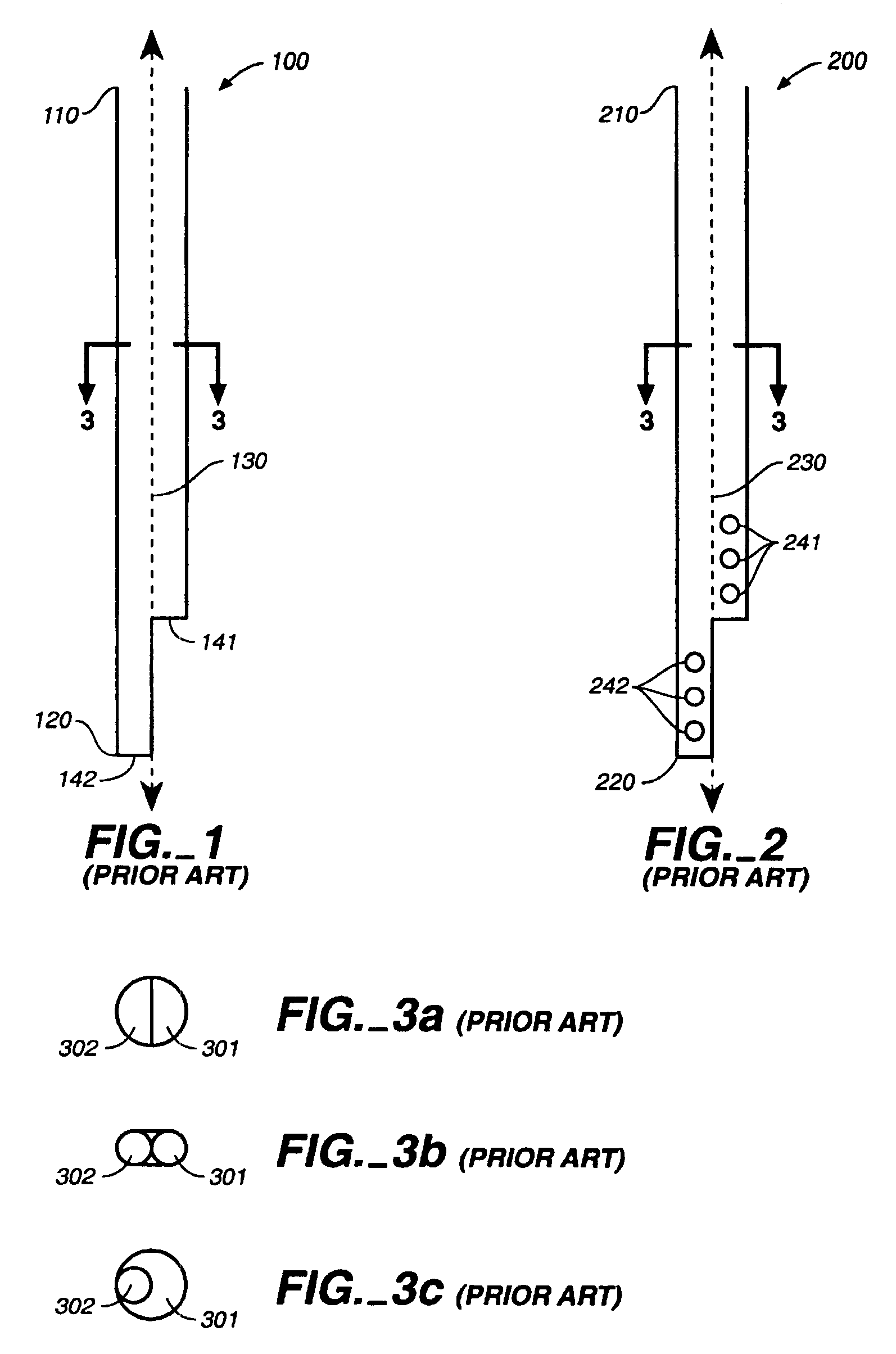
On occasion, prior art catheters, such as that shown in FIG. 1, fail to perform their intended function.
The failure modes of these catheters are numerous.
One common type of failure is occlusion of the uptake lumen end hole by the adjacent wall of the vein or by the wall of the right atrium.
This adverse action of the uptake lumen end hole either limits the flow rate of the catheter or occludes blood flow entirely through the catheter.
However, this design, in which multiple side holes are present to prevent occlusion by adjacent walls, presents a drawback of its own.
Such blood clots would occlude the lumens, leading to catheter failure.
If the uptake lumen has multiple side holes, the anticoagulant solution leaks away at the catheter tip through these multiple side holes, causing an increased risk of blood clot formation on the catheter's tip, thus causing subsequent catheter failure.
However, as detailed above, such a prior-art hemodialysis catheter retains a tendency to have its uptake lumen end hole aspirate against an adjacent wall and occlude the uptake lumen.

Method used


Image

  • Double-lumen catheter
  • Double-lumen catheter
  • Double-lumen catheter

Examples


first embodiment

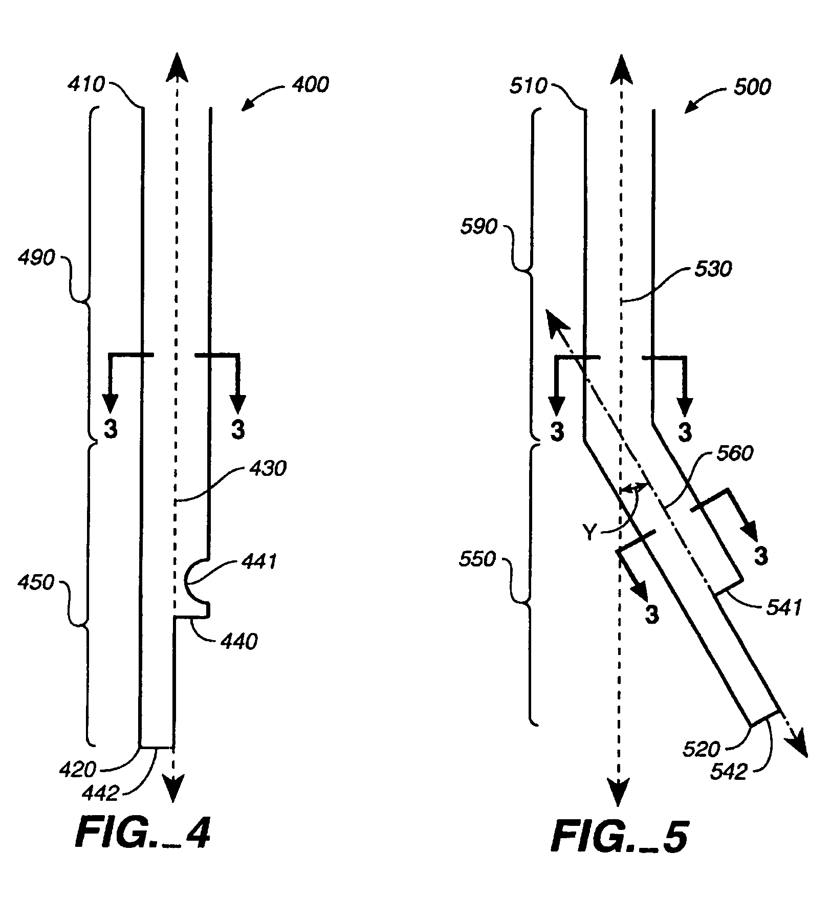
[0025]FIG. 4 is a side view of the catheter of the present invention. Catheter 400, in FIG. 4, has a proximal end 410, a distal end 420, and a central axis 430. Catheter 400 includes a shaft segment 490 (which may also herein be referred to as the intravenous portion) and a distal end segment 450. In one embodiment, distal end segment is 450 is much smaller than the shaft segment 490. (Please note that figures in this application are not drawn to size.) Central axis 430 is a straight line that runs along the length of the catheter 400, including the shaft segment 490 and distal end segment 450.

[0026]Catheter 400 includes an uptake lumen side hole 441 and a return lumen end hole 442 in the distal end segment 450. In catheter 400, uptake lumen side hole 441 is the only uptake lumen hole. Catheter 400 does not have any other uptake lumen side holes in addition to uptake lumen side hole 441. Additionally, catheter 400 does not include an uptake lumen end hole since the distal end of upt...

second embodiment

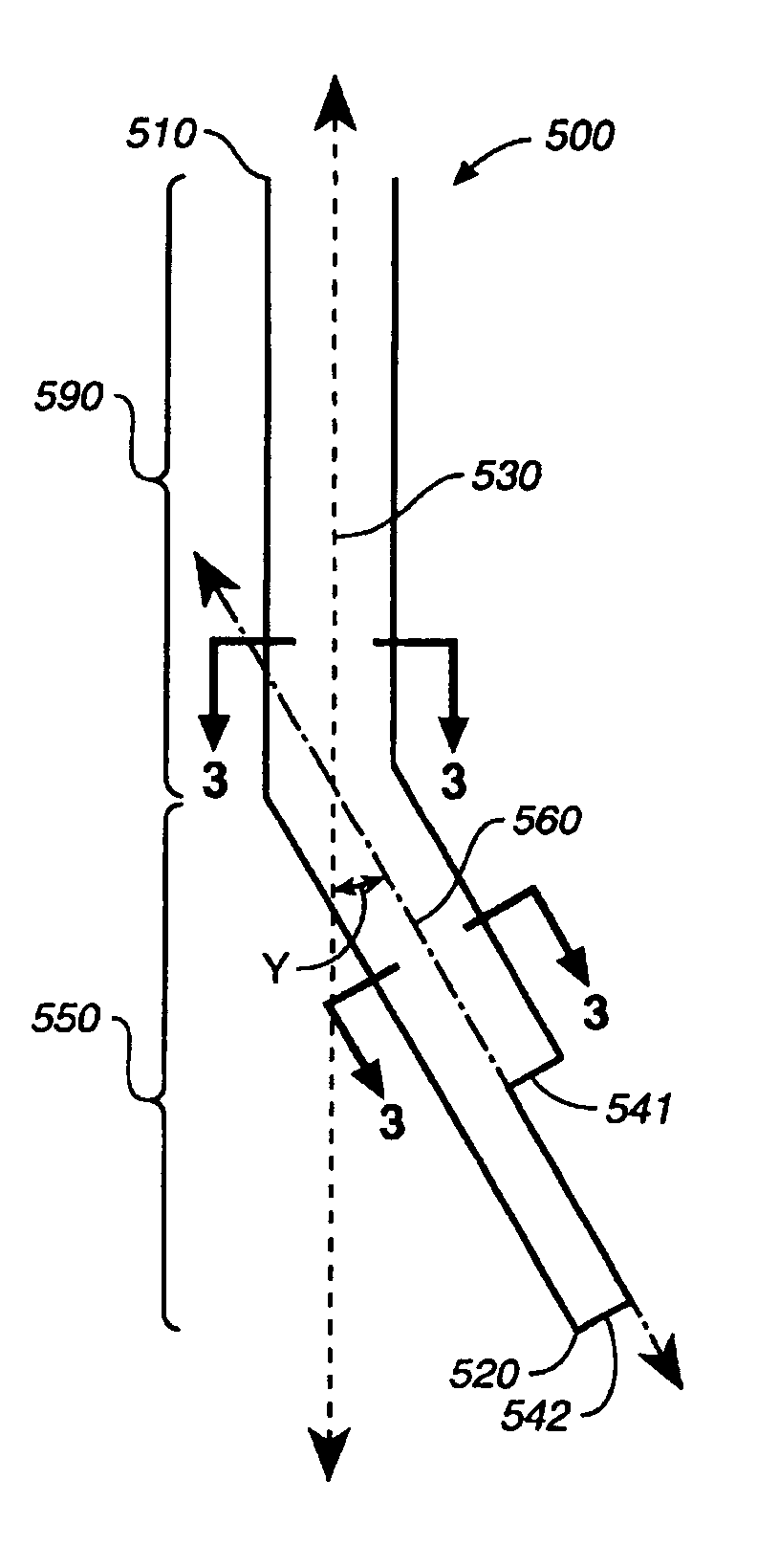
[0030]FIG. 5 is a side view of the catheter of the present invention. Catheter 500 has a proximal end 510, a distal end 520, and a central axis 530. Catheter 500 includes a shaft segment 590 and a distal end segment 550. Central axis 530 runs along the length of shaft segment 590. Distal end segment 550 includes central axis 560 which forms a non-zero angle Y with central axis 530. Thus, the distal end segment 550 is angled away from the central axis 530 of the catheter.

[0031]Angled distal end segment 550 includes both a portion of the uptake lumen and a portion of the return lumen. Three embodiments of the cross sectional view along line 3—3 in the distal end segment 550 are shown in FIGS. 3a, 3b, and 3c.

[0032]Angled distal end segment 550 includes a return lumen end hole 542 and an uptake lumen end hole 541 that is located proximally with respect to the return lumen end hole 542. Angled distal end segment 550 allows the uptake lumen end hole 541 of the uptake lumen of the catheter...

third embodiment

[0034]FIG. 6 is a side view of the catheter of the present invention. In FIG. 6, catheter 600 has a proximal end 610, a distal end 620, and a central axis 630. Catheter 600 includes a shaft segment 690 and a distal end segment 650. Central axis 630 runs along the length of shaft segment 690.

[0035]Distal end segment 650 includes an uptake lumen end segment 651 and a return lumen end segment 652. Uptake lumen end segment 651 and return lumen end segment 652 each comprise separate tubes. Uptake lumen end segment 651 has a central axis 661 that forms a non-zero angle Z with central axis 630. Thus, uptake lumen end segment 651 is angled with respect to the central axis 630. On the other hand, return lumen end segment 652 has a central axis 662 that is parallel to the central axis 630. Thus, return lumen end segment 652 is not angled with respect to the central axis 630. However, there is a non-zero angle Z between central axis 662 of the return lumen end segment 652 and central axis 661 ...


PUM


Abstract

A catheter is described. In one embodiment, the catheter includes: a shaft segment including a shaft segment uptake lumen and a shaft segment return lumen; and a distal end segment coupled to the shaft segment, the distal end segment including a distal end segment uptake lumen and a distal end segment return lumen, where the distal end segment central axis forms a non-zero angle with the shaft segment central axis when the catheter is in its unstressed configuration. In a second embodiment, the catheter includes: a shaft segment; and a distal end segment coupled to the shaft segment; where the uptake lumen distal end is terminated by a closed surface, further where the uptake lumen distal segment includes only one side hole. In a third embodiment, the catheter includes: an uptake lumen; and a return lumen; where at least a portion of the return lumen distal segment is helically coiled around the uptake lumen distal end.

Description

CROSS-REFERENCE TO RELATED APPLICATIONS[0001]This application claims the benefit of U.S. Provisional Application Ser. No. 60 / 210,294, filed Jun. 8, 2000, and entitled “Double-Lumen Catheters Used for Hemodialysis”.FIELD OF THE INVENTION[0002]The present invention relates generally to catheters and, in particular, though not exclusively, to double-lumen catheters used for hemodialysis.BACKGROUND OF THE INVENTION[0003]Hemodialysis catheters are conventionally large double-lumen catheters. Generally, the lumens must be large enough to support flow rates greater than 250 c c / min through each lumen. A hemodialysis catheter resides within a large vein within the body or within the right atrium of the heart. The end of the catheter placed into a patient's body is referred to as the distal end of the catheter, while the end connected to a dialysis machine is called the proximal end. Blood is withdrawn out of a vein via an uptake lumen of the catheter and into the dialysis machine. The uptak...

Claims


Application Information

Patent Timeline
IPC IPC(8): A61M37/00A61F7/00A61M25/00A61M3/00
CPCA61M25/0023A61M25/0026A61M25/0041A61M25/007A61M2025/0031A61M2025/0037A61M1/3661
Inventor KUHLE, WILLIAM G.
Owner BARD ACCESS SYST
Learn More