Modular sleeve yoke

Inactive Publication Date: 2007-01-16
SWAN RICHARD E
View PDF6 Cites 154 Cited by
  • Summary
  • Abstract
  • Description
  • Claims
  • Application Information

AI Technical Summary

Benefits of technology

[0008]To attain this, the present invention extends the Swan universal receiver sleeve forward above the firearm barrel to a position just short of the firearm front sight. A weaver type interface return portion may be provided on the underside of the sleeve, or left solid over the barrel in front of the receiver to accommodate solid handguards or modular, dovetailed handguards. The underside of the rear portion of the sleeve is fixedly attached to the receiver top. The underside of the forward portion of the sleeve has an upper handguard piece attached thereto. A bottom handguard piece is fitted about the bottom of the gun barrel and is attached to the upper handguard piece via a unique channel and track system. The handguard pieces are not physically connected in anyway to the gun barrel. The sleeve is self supported by the connection of the rear portion underside to the receiver top. L

Problems solved by technology

The problem with integrating laser technology to firearms is the inherent conflict between a gun barrel's physical functioning and the rigid environment required for laser operations.
The temperature of a gun barrel in use can rise to 900° F. This type of heat, as well as the physical shock on the gun barrel from firing, will quickly destroy la

Method used


Image

  • Modular sleeve yoke
  • Modular sleeve yoke
  • Modular sleeve yoke

Examples


Embodiment Construction

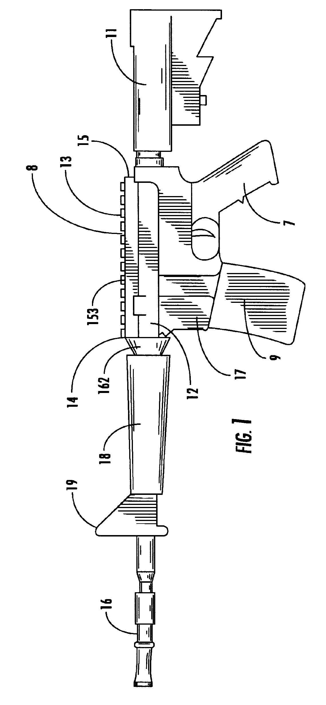
[0057]Referring to the drawings in detail wherein like elements are indicated by like numerals, there is shown in FIG. 1 an outline of a conventional combat firearm 10 having a conventional stock 11, upper receiver 12 with flat top 13, lower receiver 17, barrel 16, pistol grip 7, and magazine 9. The barrel 16 is joined to the upper receiver 12. The barrel 16 defines the forward portion of the firearm 10 and the stock 11 defines the rearward portion of the firearm 10. The longitudinal axis of the firearm 10 runs from stock 11 through receiver 12, 17 to barrel 16. The barrel 16 is joined to the forward portion 14 of the upper receiver 12, i.e., the upper receiver 12“receives” the barrel 16. The stock 11 is joined to the rear portion 15 of the upper receiver 12. The barrel 16 has protective handguards 18 about its circumference.

[0058]As shown more particularly in FIGS. 17-20, the firearm barrel 16 is detachably secured to a screw-threaded barrel port 160 at the front of the upper recei...


PUM


Abstract

A Swan universal receiver sleeve attached to the top of a firearm upper receiver and extended forward above the firearm barrel to a position just short of the firearm front sight. The underside of the rear portion of the sleeve is fixedly attached to the receiver top. The underside of the forward portion of the sleeve has an upper handguard piece attached thereto. A bottom handguard piece is fitted about the bottom of the gun barrel and is attached to the upper handguard piece. The handguard pieces are not physically connected in any way to the gun barrel. The sleeve is self supported by the connection of the rear portion underside to the receiver top. A special yoke is inserted about the barrel nut of the firearm to which the modular sleeve is attached. The special yoke reinforces the modular sleeve while keeping the firearm barrel free floating.

Description

[0001]This application is a C-I-P of Ser. No. 10 / 007,590 filed Dec. 10, 2001, which claims benefit of Prov. No. 60,274,147 filed Mar. 9, 2001.BACKGROUND OF THE INVENTION[0002]This invention relates to integration means, and more particularly to a device added to a firearm for incorporating ancillary equipment.[0003]As the field of combat and commercial weaponry expands, numerous add-on enhancements have become available for attachment to standard firearms thereby significantly upgrading the capability of the firearm. Various methods and means have been developed for interfacing the various add-on enhancements to firearms. Applicant's U.S. Pat. No. 5,142,806, incorporated herein by reference, discloses a universal receiver sleeve having an upper interface portion with standard, universal dimensions regardless of the firearm and having a lower interface portion specific to a particular firearm.[0004]Although the principles of the above identified patented device are generally applicab...

Claims


Application Information

Patent Timeline
IPC IPC(8): F41C23/00F41C23/16F41G1/387
CPCF41C23/00F41C23/16F41G11/003
Inventor SWAN, RICHARD E.
Owner SWAN RICHARD E
Why Eureka
Try Eureka