Method for sharpening bedknives

Inactive Publication Date: 2007-02-20
SCOTT KEITH M
View PDF7 Cites 1 Cited by
  • Summary
  • Abstract
  • Description
  • Claims
  • Application Information

AI Technical Summary

Benefits of technology

[0010]This object and others which will become apparent upon a reading of the following specification and claims is achieved by mounting each of a pair of electromagnets to a respective clamping pedestal, secured at spaced locations to a support rail of a bedknife grinder. Each of the electromagnets has a pair of orthogonal locating surfaces fixed thereto, one surface disposed in a vertical plane, and the other in a horizontal plane. The locator surfaces are ground by traversing the grinder wheel across each surface such as to establish precisely aligned orthogonal surfaces which are parallel to the line of movement of the grinder carriage on its way.
[0011]The rear edge and bottom surface of each bedknife is placed in position abutting the respective locating surfaces, and the electromagnets thereafter energized to chuck the bedknife in an acc

Problems solved by technology

Bedknives become dulled with use, such as to require periodic sharpening and truing of the surface defining the clearance space with the blades of the reel blade array.
This manual alignment adjustment is tedious and time consuming, and subject to error.
In addition the bedknif

Method used


Image

  • Method for sharpening bedknives
  • Method for sharpening bedknives
  • Method for sharpening bedknives

Examples


Embodiment Construction

[0020]In the following detailed description, certain specific terminology will be employed for the sake of clarity and a particular embodiment described in accordance with the requirements of 35 USC 112, but it is to be understood that the same is not intended to be limiting and should not be so construed inasmuch as the invention is capable of taking many forms and variations within the scope of the appended claims.

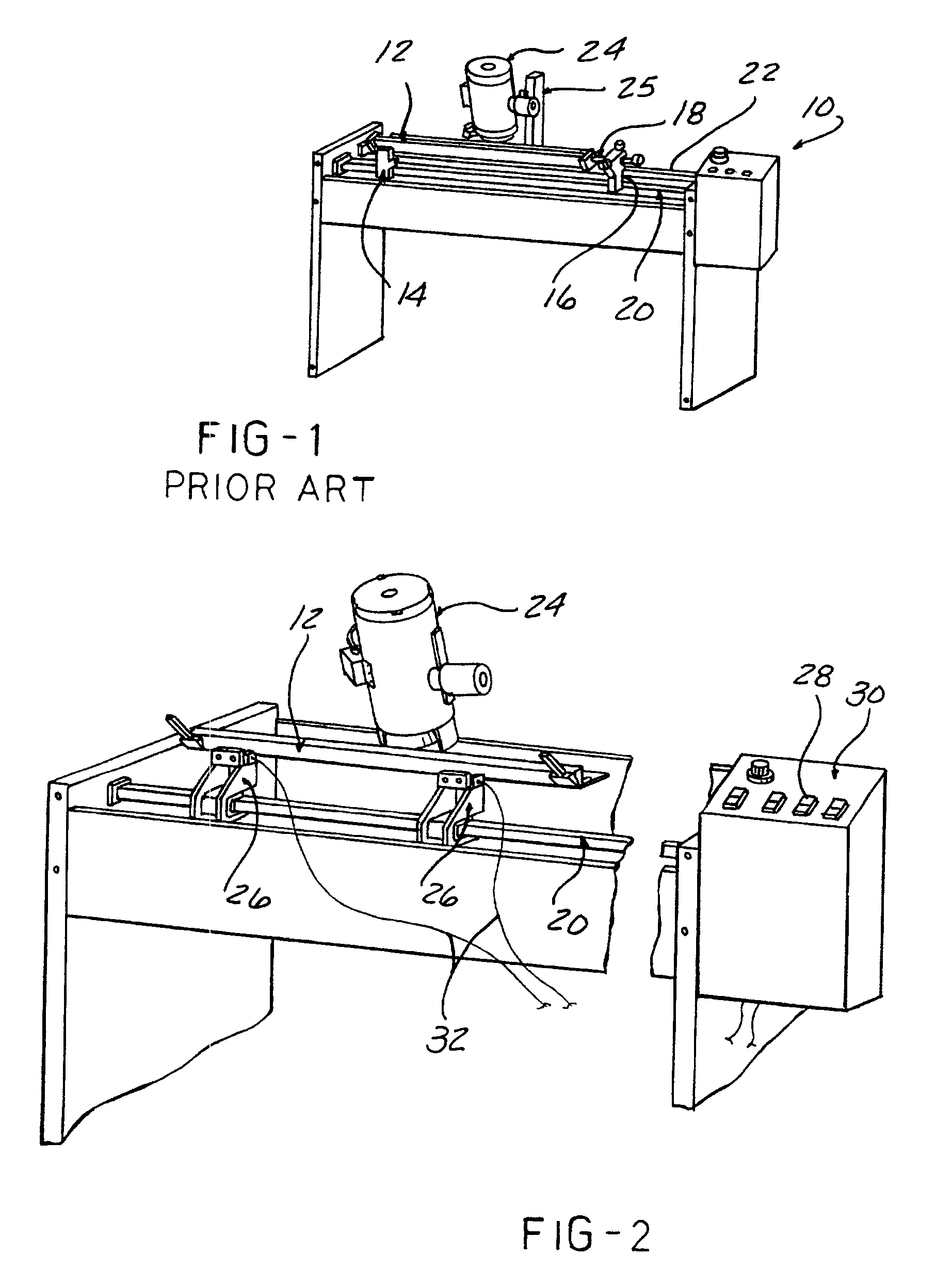
[0021]Referring to FIG. 1, a prior art bedknife grinder 10 is depicted in which a bedknife 12 is mounted between centers 14 and 16 engaging the pivot points 18 on which the bedknife 12 is supported in the mower. The centers 14, 16 are clamped to a support rail 20 extending parallel to ways 22 on which a grinding motor 24 carriage 25 is traversed by means of a power screw (not shown). In order to properly set up the machine for grinding, the bedknife 12 axis is aligned with the carriage ways 22 by means of a gauge and adjustment of the right hand center 16. This requires ...


PUM


Abstract

A method of sharpening bedknives for reel type mowers by installing sets of locator surfaces in a bedknife grinder, grinding the surfaces with the grinder to be aligned and parallel, installing a bedknife located against surfaces in both sets, and electromagnetically locking the bedknife in position while grinding the edge to be sharpened. The bedknife is adjusted to be aligned with the reel blades by adjusting the bedknife pivots in the mower.

Description

[0001]This is a continuation of Ser. No. 08 / 795,902 filed on Feb. 5, 1997, now abandoned, which is a continuation of Ser. No. 08 / 507,942, filed on Jul. 27, 1995 now abandoned.BACKGROUND OF THE INVENTION[0002]This invention concerns sharpening apparatus and more particularly bedknife grinders for sharpening the bedknife used with reel type mowers.[0003]Reel mowers consist of a set of helically formed blades arranged in a generally cylindrical shape. The blades are rotated against a bedknife closely positioned along the perimeter of the reel blade array. Grass being mowed is sheared as each segment of the blades rotate to progressively reduce the clearance with the bedknife, shearing the grass blades between the blades and the bedknife.[0004]Bedknives become dulled with use, such as to require periodic sharpening and truing of the surface defining the clearance space with the blades of the reel blade array.[0005]Bedknives are mounted to the mower op a pair of pivotal mounts fixed to e...

Claims


Application Information

Patent Timeline
IPC IPC(8): B24B1/00B21D39/03B23P11/00B24B3/55
CPCB24B3/55Y10T29/49826Y10T29/49998
Inventor SCOTT, KEITH M.
Owner SCOTT KEITH M
Why Eureka
Try Eureka