
Window frame for manufactured housing

a technology for manufactured housing and window frame, which is applied in the direction of building components, applications, and closure members, etc., can solve the problems of small misalignment of the end of the window frame, the expansion and contraction of vinyl and aluminum, and the problem of lap siding manufacturers

Inactive Publication Date: 2008-02-05
SEALMASTER
View PDF30 Cites 10 Cited by
  • Summary
  • Abstract
  • Description
  • Claims
  • Application Information

AI Technical Summary

Benefits of technology

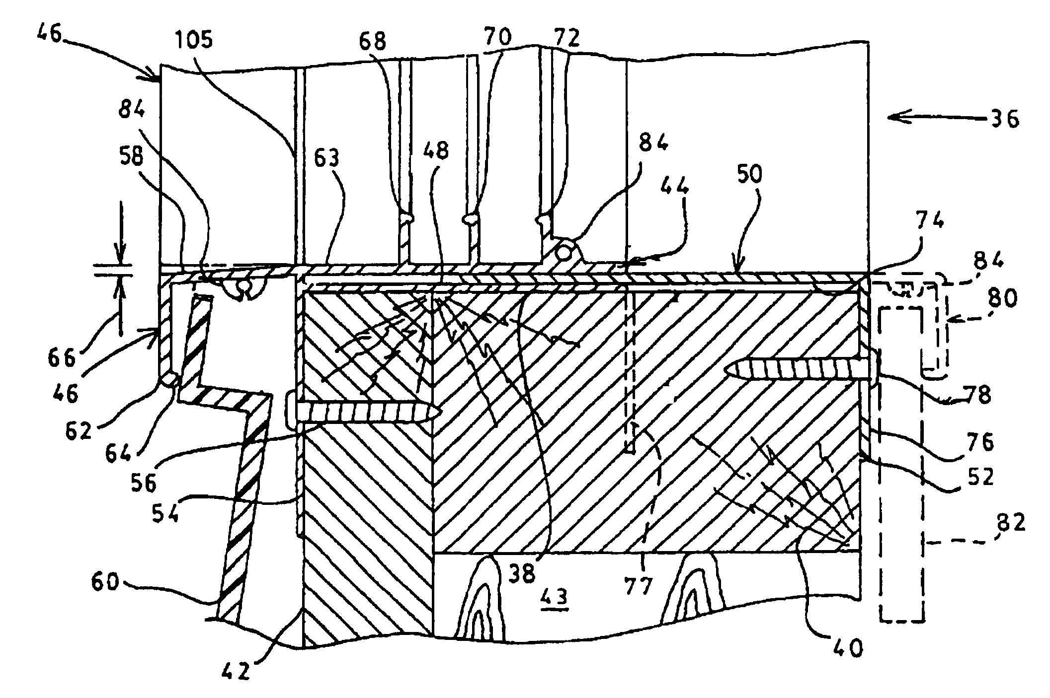
[0013]In accordance with the present invention, there is provided a window frame for being received in an opening of a wall of a structure, the window frame for receiving and supporting at least one window. This frame has a body portion circumscribing the wall opening with a window receptor intermediate an inner portion of the body portion extending toward an inner wall of the structure and an outer portion of the body portion extending proximate an outer frame wall of the structure. A J-rail portion is integrally formed with the body portion so as to project outwardly from the body portion to rece...

Problems solved by technology

The manufacturers of the homes with lap siding were faced with the problem of encasing the ends of the vinyl / aluminum lap siding to exclude rain.
Also, there is often small misalignment of ends of the siding since the pieces are cut from strips, and both vinyl and aluminum expand and contract significantly under extremes of temperature.
There is also a problem that there is separate material that must be carried to (or stored at) a site of fabrication.
The main problem is the extra time that is required for its installation-measuring, cutting and fastening of separate pieces.
Unless significant care is taken during the cutting, bending and fastening of the J-rail, gaps can occur such that the finished product is less than aesthetically attractive.
Thus, although the other structural portions of manufactured homes have changed, the window manufacturers apparently did not consider other known windows to be of use for this type of siding.

Method used


Image

  • Window frame for manufactured housing
  • Window frame for manufactured housing
  • Window frame for manufactured housing

Examples


Embodiment Construction

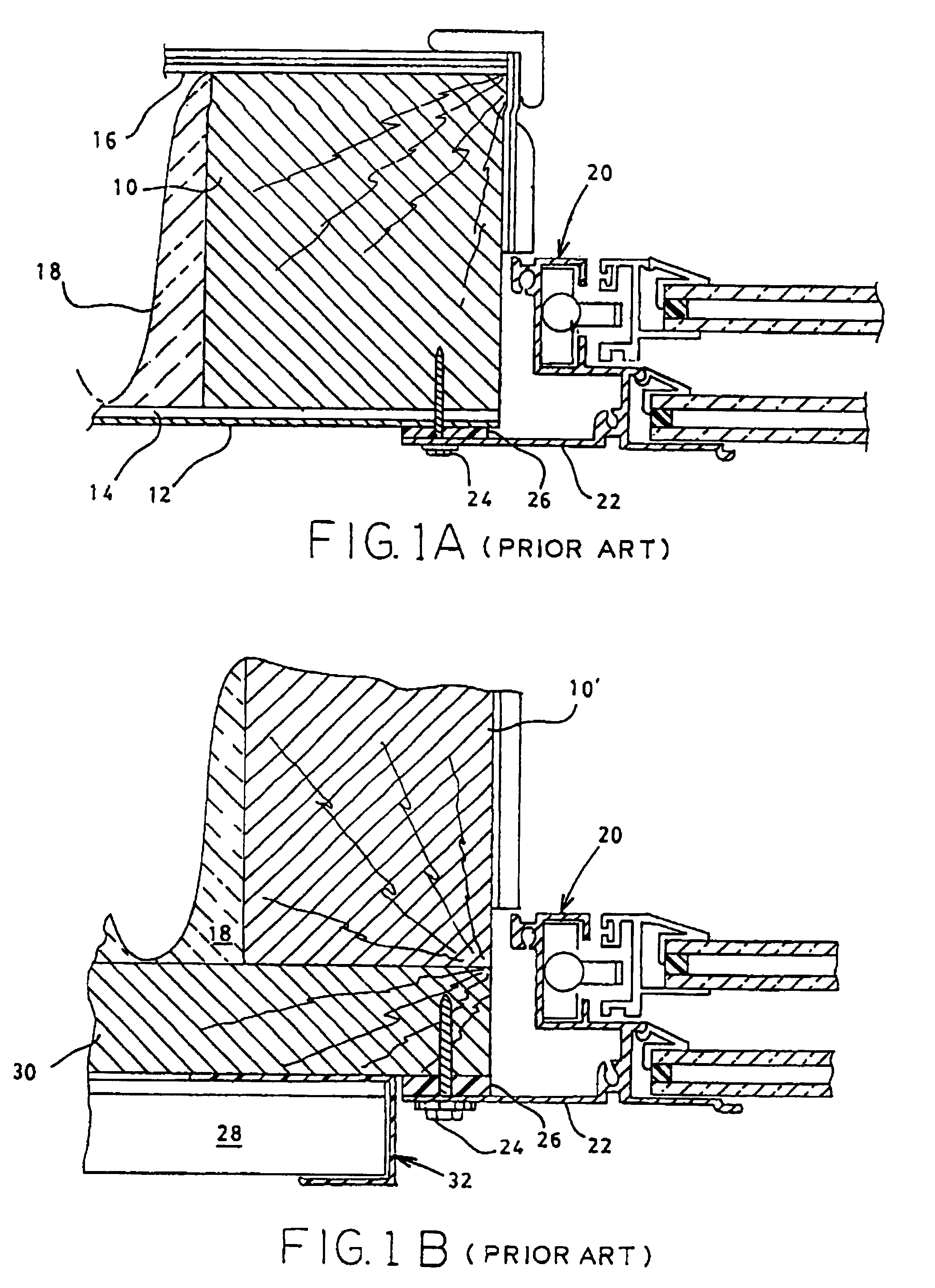
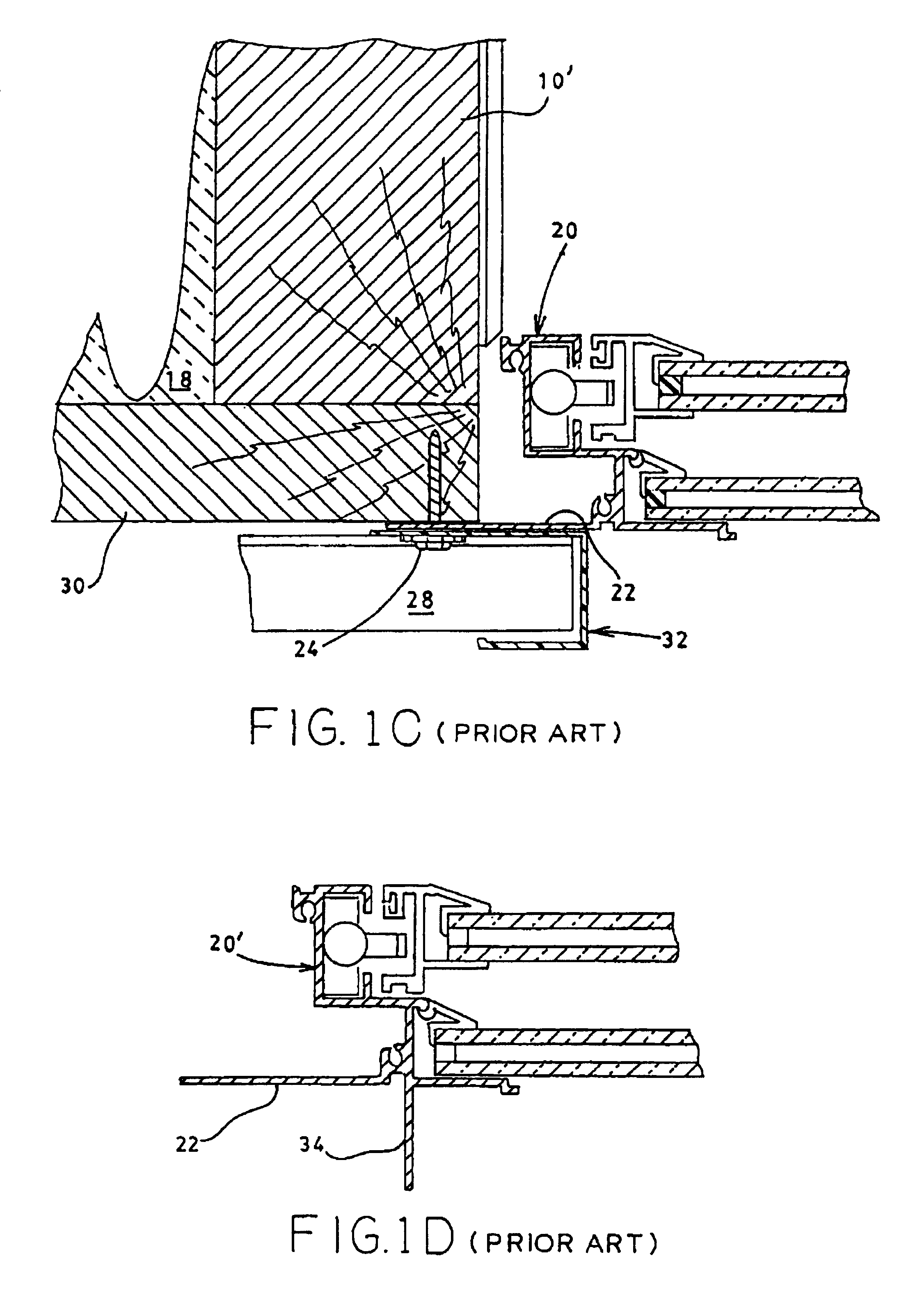
[0021]The departure of the present invention from the prior art of window / siding relationships will be better understood by first considering the construction that had existed prior to the present invention. Therefore, referring to FIG. 1A, shown therein is an early wall / window structure as utilized in manufactured housing. The frame of the housing unit was typically a series of 2 in.×2 in. elements 10 that were covered on the exterior with sheet metal 12 which was, in some embodiments, embossed or corrugated to give some improved visual appearance. There may be, or may not be, a thin sheeting layer 14 The inner surface of this building frame was typically covered with panelling 16, and the void between the layers was filled with insulation 18. At places where windows were desired, an opening was cut through the wall of appropriate size, and a prefabricated window unit 20 was inserted having a perimeter flange 22. Although this FIG. 1A (and FIGS. 1B-1D) illustrate upper and lower do...


PUM

PropertyMeasurementUnit
Temperatureaaaaaaaaaa
Widthaaaaaaaaaa

Abstract

A window frame construction particularly useful in a manufactured housing unit to provide a structure for receiving and supporting at least one window and to provide coverage of ends of siding applied to the exterior of the housing unit. The window frame includes a window body member to generally circumscribe an opening in the housing unit, with a J-rail return member integrally formed therewith to provide a flange member for attachment of the window frame to the housing unit and to cover and secure ends of the siding in a slot formed between the flange member and the return member of the J-rail return. The return member has sufficient width to cover the siding ends even when the siding contracts during lowered temperatures. The window frame, in the preferred form, is constructed from extruded vinyl, and it is used principally for vinyl siding.

Description

[0001]This is a continuation application of application Ser. No. 07 / 934,257, filed Aug. 25, 1992, now U.S. Pat. No. 5,392,574, issued Feb. 28, 1995, which is a continuation-in-part application of Ser. No. 07 / 570,818, filed Aug. 22, 1990, now abandoned, which is a continuation-in-part application of Ser. No. 07 / 338,306, filed Apr. 17, 1989, now abandoned, which is a continuation-in-part application of Ser. No. 07 / 083,225, filed Aug. 10, 1987, <?delete-start id="DEL-S-00001" date="20080205" ?>abandoned<?delete-end id="DEL-S-00001" ?> <?insert-start id="INS-S-00001" date="20080205" ?>now U.S. Pat. No. 4,747,753<?insert-end id="INS-S-00001" ?>.TECHNICAL FIELD[0002]This invention relates to a window frame construction for principal use in manufactured housing, the frame receiving and supporting at least one window, the frame for being mounted in a window opening provided in a wall structure of the manufactured unit. This particular frame includes an integrally ...

Claims


Application Information

Patent Timeline
IPC IPC(8): E06B1/26E06B1/36E06B1/30E06B1/62
CPCE06B1/30E06B1/62E06B2001/628Y10S49/02
Inventor SAYERS, LELAND D.
Owner SEALMASTER
Learn More