Device for attaching a dispenser member to a receptacle
What is Al technical title?
Al technical title is built by PatSnap Al team. It summarizes the technical point description of the patent document.
a technology for attaching devices and dispensers, which is applied in the field of devices for attaching dispensers to receptacles, can solve problems such as preventing proper overall assembly, hoop being forced away, and affecting the overall assembly of the devi
Inactive Publication Date: 2011-07-19
APTAR FRANCE SAS
View PDF113 Cites 8 Cited by
Summary
Abstract
Description
Claims
Application Information
AI Technical Summary
This helps you quickly interpret patents by identifying the three key elements:
Problems solved by technology
Method used
Benefits of technology
[0049](4) exerting a first force F1 on the hoop which bears against the guide wall of the fixing ring via the bottom end of the projection and which pushes the fixing ring against the neck of the receptacle, the snap-fastening means first splaying part under the effect of the force F1 prior to snap-fastening to the flange of the neck of the receptacle; and
[0050](5) exerting on the hoop a second force F2 greater than the first force F1, the second force F2 being sufficient to cause the hoop to move relative to the fixing ring to a final position so as to further engage the fixing ring in a force fit with a portion of the hoop being located adjacent the snap-fastening means, the hoop thereby preventing the snap-fastening means of the fixing ring from splaying apart.
Problems solved by technology
Conventional attachment devices suffer from certain drawbacks.
In particular, when the force exerted on the hoop is not uniformly distributed around its periphery, there is a risk of the hoop being forced away from its vertical position in the assembly machine so that the hoop becomes cocked or slanted and engaged obliquely on the fixing ring, thereby preventing proper overall assembly.
Method used
Image
Click on the blue label to locate the original text in one second.
Reading with bidirectional positioning of images and text.
Examples
Embodiment Construction
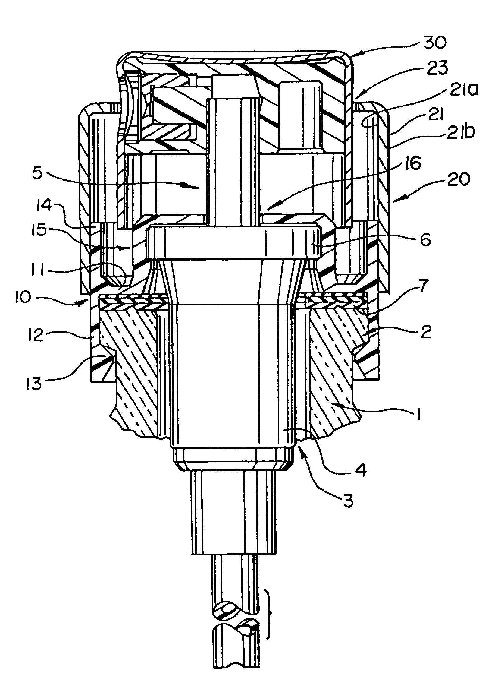
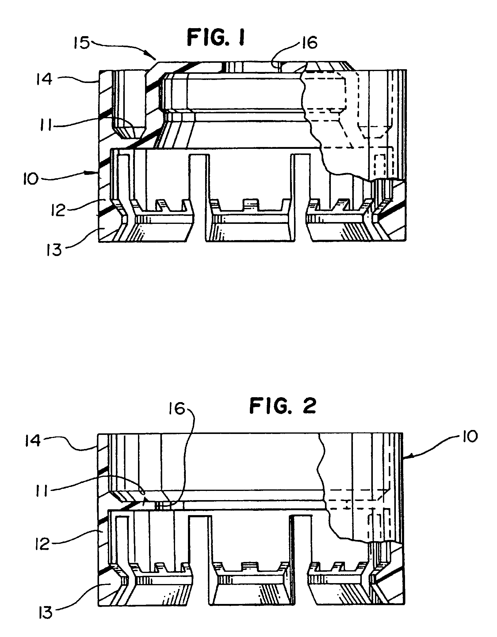
[0067]In one aspect of the invention, an annular attaching ring or fixing ring is provided to attach or fix a dispenser member on the neck of a container or other receptacle containing a substance to be dispensed. Two variants or embodiments of such a fixing ring 10 are shown in FIGS. 1 and 2.
[0068]With reference to FIG. 1, the fixing ring 10 includes a bottom portion designed to cooperate with the neck of the receptacle and includes a top portion designed to cooperate with the dispenser member. The bottom portion includes fixing means 12, 13 for holding, engaging, or attaching the ring 10 to the neck. The means 12, 13 may be snap-fastening means. Preferably, the snap-fastening means 12, 13 include snap-fastening tabs 12 and engaging members, catches, or feet 13. The tabs 12 are preferably distributed around the circumference of the ring 10 and extend parallel to the central axis of the ring 10 (downwardly in FIGS. 1 and 2).
[0069]Each of the tabs 12 preferably includes a snap-fasten...
PUM
Abstract
An attaching ring or fixing ring is provided for attaching or fixing a dispenser member to a neck of a receptacle containing a substance to be dispensed. The ring is annular and has a bottom portion and a top portion. In a preferred embodiment, the bottom portion includes snap-fastening tabs for fixing the ring to the neck. The top portion includes an opening for the dispenser and a surrounding structure for securing the dispenser member to the neck. The top portion further includes at least one guide wall element extending parallel to the longitudinal axis of the dispenser member and around the periphery of the fixing ring substantially in line with the snap-fastening tabs. A hoop can be provided for preventing the tabs from splaying apart. The hoop can include an internal projection, such as a vertical rib or a thread.
Description
[0001]This is a reissue of U.S. Pat. No. 6,543,648, issued on Apr. 8, 2003 from U.S. patent application Ser. No. 10 / 136,211, filed May 1, 2002. [0002]This is a continuation of U.S. patent application Ser. No. 09 / 654,018, filed Sep. 1, 2000 now U.S. Pat. No. 6,409,049, which is a continuation of U.S. patent application Ser. No. 09 / 099,684, filed Jun. 18, 1998, now U.S. Pat. No. 6,186,359, issued Feb. 13, 2001, which is a divisional of U.S. patent application Ser. No. 08 / 725,934, filed Oct. 7, 1996, now U.S. Pat. No. 5,799,810, issued Sep. 1, 1998, which is a divisional of U.S. patent application Ser. No. 08 / 311,041, filed Sep. 22, 1994, now U.S. Pat. No. 5,562,219, issued Oct. 8, 1996.[0003]The present invention relates to a device for attaching, and to a method for attaching, a dispenser member, such as a pump or a valve, to the neck of a receptacle containing a substance to be dispensed.BACKGROUND OF THE INVENTION[0004]It is known that a dispenser or dispenser member can be attache...
Claims
Application Information
Patent Timeline
Application Date:The date an application was filed.
Publication Date:The date a patent or application was officially published.
First Publication Date:The earliest publication date of a patent with the same application number.
Issue Date:Publication date of the patent grant document.
PCT Entry Date:The Entry date of PCT National Phase.
Estimated Expiry Date:The statutory expiry date of a patent right according to the Patent Law, and it is the longest term of protection that the patent right can achieve without the termination of the patent right due to other reasons(Term extension factor has been taken into account ).
Invalid Date:Actual expiry date is based on effective date or publication date of legal transaction data of invalid patent.