Ignitor

A technology for an appliance and an intermediate housing, which is applied in the directions of combustion ignition, igniter with fuel, combustion method, etc., can solve the problems of complicated assembly, difficult assembly, and difficult ignition, etc. The effect of a reliable lock state

Inactive Publication Date: 2007-10-17
TOKAI
View PDF13 Cites 0 Cited by
  • Summary
  • Abstract
  • Description
  • Claims
  • Application Information

AI Technical Summary

Problems solved by technology

[0005] However, in the former locking mechanism, since the locking member and the urging member composed of the spring that springs the locking member to the locking direction are assembled on the appliance body in different ways, it is difficult to assemble these members, which becomes Barriers to achieving increased productivity in mass production
In addition, multi-stage operation is required during the ignition operation, so there are also difficulties in operability.
[0006] The above-mentioned prior art has the problem that it is complicated work to assemble the two parts such as the locking member and the urging member in a different way from the operating member, and it is necessary to deform the urging member to a certain extent. It is difficult to efficiently assemble these parts into the appliance body with other parts
Moreover, the unlocking operation during the ignition operation in the normal use state is also because the releasing operation part is in the shape of a protrusion separated from the operating member, so the releasing operation and the pushing operation of the operating member are not consistent, and become multi-stage complicated. operation, it is sometimes difficult to achieve a stable ignition
[0007] In the latter locking mechanism, since its structure is such that the arm of the locking member extends along the moving direction of the operating member, it will interfere with the piezoelectric assembly inside the operating member, so there is relatively little space in the inner space of the operating member. In a narrow case, the movement range of the locking member is small, and it is difficult to obtain stable operability in the locked position and the unlocked position. In addition, since the interference portion between the arm and the piezoelectric unit is small, it is difficult to ensure a reliable locked state and In the released state, the function may be affected if the front end is worn out after repeated use

Method used


Image

  • Ignitor
  • Ignitor
  • Ignitor

Examples


no. 1 Embodiment approach

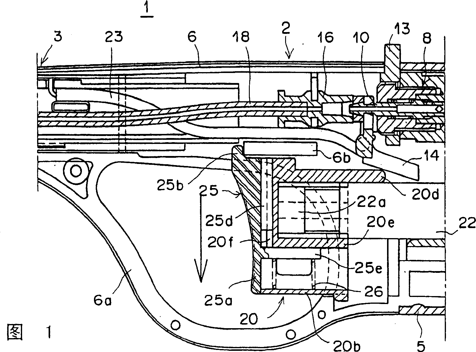
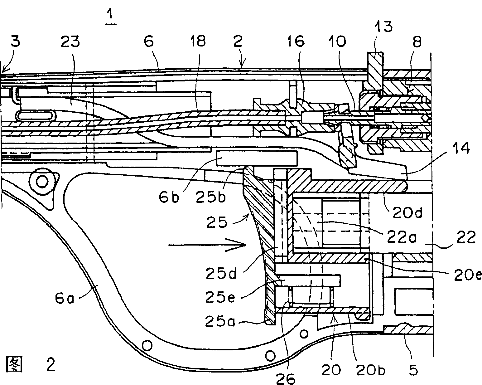
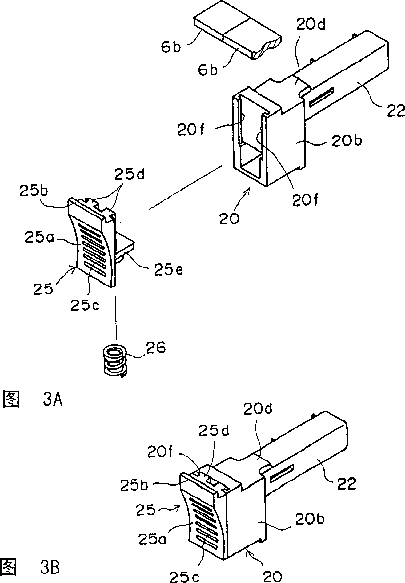
[0035] Fig. 1~Fig. 3B shows the igniter constituted by the ignition rod of this embodiment, Fig. 1 is a sectional view of main parts, Fig. 2 is a sectional view of an operating state, and Fig. 3A and Fig. 3B are perspective views of a locking mechanism.

[0036]The igniter (ignition rod) 1 of the present embodiment is composed of a device body 2 and an extended tip portion 3 extending in a rod shape (the tip portion is omitted in the figure). The appliance body 2 is formed of a synthetic resin-molded gas storage tank portion 5 and an intermediate case 6. The intermediate case 6 is divided longitudinally at approximately the center in front of the gas storage tank portion 5. FIGS. 1 and 2 show the intermediate case. 6 for one.

[0037] A gas storage chamber (not shown in the figure) is provided on the base end side (right side of the figure) of the appliance body 2 for storing high-pressure gas such as butane gas in the gas storage tank portion 5. A valve mechanism 8 is provid...

no. 2 Embodiment approach

[0053] 4 is a sectional view of main parts of an ignition device provided with a locking mechanism according to another embodiment; FIG. 5 is a sectional view showing an operating state; and FIGS. 6A and 6B are perspective views of the locking mechanism.

[0054] The lock mechanism in the igniter 11 of this embodiment is different from that of the first embodiment, except that the lock member 27 and the form of the engaging portion 6c are different, the operating member 20, the piezoelectric assembly 22 (ignition device), and the biasing member 26 are all the same. The configuration is the same, so the same parts are given the same symbols and their descriptions are omitted.

[0055] In this embodiment, the locking position and the unlocking position of the locking member 27 are configured opposite to those of the locking member 25 of the first embodiment described above.

[0056] The locking member 27 also serves as an operating portion of the operating member 20 , is slidabl...

no. 3 Embodiment approach

[0064] Fig. 7 is a sectional view of main parts of an ignition device provided with a lock mechanism according to still another embodiment of the present invention, and Fig. 8 is a sectional view showing a state in which the lock is released.

[0065] The igniter of this embodiment (another embodiment of the ignition rod) 12 is composed of an appliance body 4 different in shape from the above-mentioned embodiment and a rod-shaped extension front portion 7 extending from the center of the appliance body 4 (the front end portion is omitted in the figure). )constitute. The appliance body 4 is formed of a synthetic resin molded gas storage tank portion 9 and an intermediate case 60 split longitudinally at the front substantially in the center. FIGS. 7 and 8 show one of the intermediate cases 60 . The intermediate case 60 is formed in a circular shape with a finger insertion window 60a opened in the center.

[0066] The gas storage tank portion 9 on the base end side (the right si...


PUM


Abstract

In an igniter (1) which is ignited by operation of an actuator 20 and is provided with a lock member (25) which locks an actuator (20) when the igniter is unused and automatically returns to the locking position after use of the igniter, operability is improved and assembly is simplified. A lock member (25) which is moved in the igniting direction together with the actuator (20) is installed to be movable between a locking position and a lock release position. A lock portion (25b) of the lock member (25) extending in the locking direction interferes with an engagement portion of the igniter body to lock igniting action of the actuator (20). The lock member (25) is urged to the locking position by an urging member (26). With the lock released by operation of the lock member (25), the actuator (20) is slid together with the lock member (25) to ignite the igniter (1).

Description

technical field [0001] The present invention relates to an igniter in which flame is ejected from a gas nozzle by an ignition operation of an operating member. Normally, the locking member is engaged with the device body to lock the ignition; It is a mechanism that can release the ignition lock and start the ignition without disengagement. Background technique [0002] Although the igniter is a convenient appliance that can be easily ignited by pushing the fire rod into the operating member, it is required to be provided with a locking mechanism that cannot be accidentally ignited or accidentally ignited, so it has been proposed so far. Igniters with various mechanisms. [0003] For example, Japanese Unexamined Patent Publication No. 8-61673 discloses an igniter having a structure in which a locking portion provided so as to be movable in a direction intersecting with the moving direction of the operating member interferes with a part of the operating member. The locking m...

Claims


Application Information

Patent Timeline
Patent Type & Authority Patents(China)
IPC IPC(8): F23Q2/28F23Q2/36
CPCF23Q2/287
Inventor 中村保昭森下利教
Owner TOKAI
Why Eureka
Try Eureka