Portable braking force tester for car

A small car, braking force technology, used in vehicle testing, force/torque/work measuring instruments, braking safety systems, etc. problems, to achieve the effect of easy self-detection, easy operation, and easy portability

Inactive Publication Date: 2007-10-17
HUNAN AGRICULTURAL UNIV
View PDF3 Cites 0 Cited by
  • Summary
  • Abstract
  • Description
  • Claims
  • Application Information

AI Technical Summary

Problems solved by technology

[0003] At present, the detection methods of automobile braking performance mainly include road test and bench test. No car repair shop can reach this scale
Therefore, it is inconvenient to test the braking system

Method used


Image

  • Portable braking force tester for car
  • Portable braking force tester for car
  • Portable braking force tester for car

Examples


Embodiment Construction

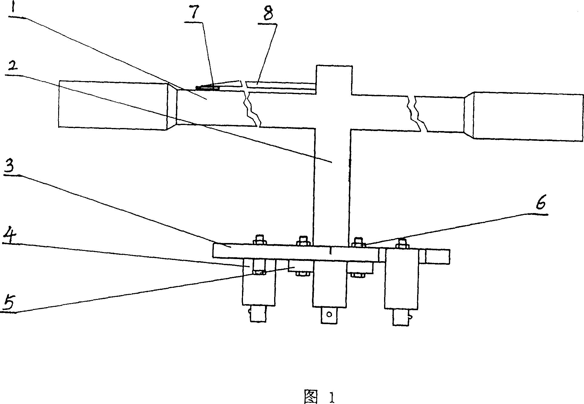
[0020] According to Figures 1 to 3 and the portable small car braking force tester of the present invention with the above structure, the two-way booster rod 1 and the rigid force transmission shaft 2 of this embodiment are integrally forged, and the center of the two-way booster rod 1 is vertically connected to the rigid force transmission shaft 2. The left end of two-way booster rod 1 fixes instrument panel 7; The right end of instrument pointer 8 is provided with screw thread, and instrument pointer 8 threads are tightly connected to the upper end of above-mentioned rigid power transmission shaft.

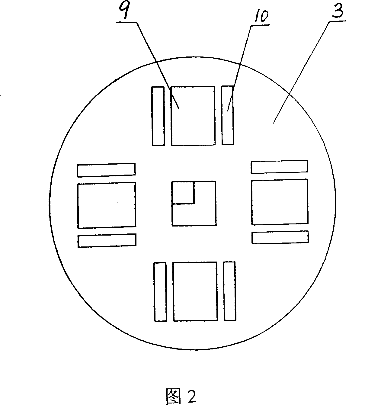
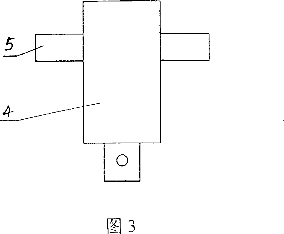
[0021] Referring to FIG. 2 , four wide grooves 9 and eight narrow grooves 10 are symmetrically distributed on the hub sleeve 3 . The eight narrow grooves 10 are arranged in pairs on both sides of each wide groove 14 . The bolt 6 passes through the narrow groove 10 and the ear hole of the lug 5 of the sliding sleeve 4 and is connected with the hub sleeve 3 , thereby realizing th...


PUM


Abstract

A tester for testing brake force of car is prepared by connecting two - way forcing rod to rigid force transmitting shaft with its top end being connected to instrument board and its bottom end being connected to a wheel hub casing disc , distributing wide and narrow slots with slip case on said casing disc , connecting slip case to wheel hub casing disc by passing its lug through bolt and narrow slot for realizing the positioning at any position .

Description

technical field [0001] The invention relates to a portable small car braking force tester, a portable and manpower testing device for small car brake braking force. Background technique [0002] With the development of society and the improvement of people's living standards, the number of automobiles has increased rapidly, and the absolute number of traffic accidents has also increased. And in all traffic accidents, the proportion of the traffic accidents caused by the problem of braking system is very large. Therefore, whether the brake system of the car is working normally and whether the brakes of the car can generate enough braking force are the key to ensure the safety of the car, and it is also an indicator for the country to carry out mandatory testing on the car. As a car owner and driver, he knows the need to check the brakes of the car frequently. [0003] At present, the detection methods of automobile braking performance mainly include road test and bench test...

Claims


Application Information

Patent Timeline
Patent Type & Authority Patents(China)
IPC IPC(8): G01L5/28G01M17/007B60T17/22
Inventor 岳大军赵凯慧赵洋岳柳肖明涛
Owner HUNAN AGRICULTURAL UNIV
Why Eureka
Try Eureka